Sign In
Upload
Manuals
Brands
TOSHIBA Manuals
Microcontrollers
TXZ
TOSHIBA TXZ Manuals
Manuals and User Guides for TOSHIBA TXZ. We have
1
TOSHIBA TXZ manual available for free PDF download: Reference Manual
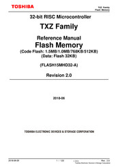
TOSHIBA TXZ Reference Manual (120 pages)
32-bit RISC Microcontroller
Brand:
TOSHIBA
| Category:
Microcontrollers
| Size: 3.63 MB
Table of Contents
Table of Contents
2
Preface
8
Related Documents
8
Conventions
9
Terms and Abbreviation
11
1 Outline
12
Table 1.1 Functional Description (Code Flash)
12
Table 1.2 Functional Description (User Information Area)
13
Table 1.3 Functional Description (Data Flash)
13
Figure 1.1 the Example of a Memory Map
14
Memory Map
14
2 Configuration
15
Block Diagrams
15
Figure 2.1 the Block Diagrams of a Flash Memory
15
Table 2.1 Signal List
15
Configuration of Code Flash
16
Unit of the Composition
16
Block Configuration
16
Table 2.2 Block Configuration of 1536KB Code Flash
16
Table 2.3 Block Configuration of 1024KB Code Flash
18
Table 2.4 Block Configuration of 768KB Code Flash
19
Table 2.5 Block Configuration of 512KB Code Flash
20
Page Configuration
21
Table 2.6 Page Configuration of 1536KB Code Flash
21
Table 2.7 Page Configuration of 1024KB Code Flash
22
Table 2.8 Page Configuration of 768KB Code Flash
23
User Information Area Configuration of Code Flash
24
Program/Erase Time of Code Flash
24
Table 2.9 Page Configuration of 512KB Code Flash
24
Table 2.10 User Information Area Configuration of Code Flash
24
Memory Capacity and the Configuration
25
Table 2.11 Memory Capacity and the Configuration
25
Block Configuration of Data Flash
26
Configuration of Data Flash
26
Table 2.12 Block Configuration of 32 KB Data Flash
26
Unit of the Composition
26
Page Configuration
27
Table 2.13 Page Configuration of 32KB Data Flash
27
Memory Capacity and the Configuration
28
Program/Erase Time of Data Flash
28
Table 2.14 Memory Capacity and the Configuration
28
3 Function Description and Functional Explanations
29
Table 3.1 JEDEC Compliant Functions
29
Code Flash
30
Command Sequence
30
List of Command Sequence
30
Table 3.2 Flash Memory Access Using the Internal CPU (Code Flash)
30
Address Bit Configuration in the Bus Write Cycle (Code Flash)
32
Table 3.3 Address Bit Configuration in the Bus Write Cycle (Code Flash)
32
Area Address (AA), Block Address (BA): Code Flash
34
Protect Bit Assignment (PBA): Code Flash
34
Table 3.4 Protect Bit Programming Address
34
ID-Read Code (IA, ID): Code Flash
36
Memory Swap Bit Assignment (MSA)
36
Table 3.5 ID-Read Command Code Assignment and the Code Contents
36
Table 3.6 Setting Values Assigned to [FCSWPSR] Using Memory Swap Command, and Example of Address
36
Command Sequence
37
Data Flash
37
List of Command Sequence
37
Table 3.7 Command Sequence (Data Flash)
37
Address Configuration in the Bus Write Cycle (Data Flash)
38
Table 3.8 Address Bit Configuration in the Bus Write Cycle (Data Flash)
38
Area Address (AA), Block Address (BA)
39
ID-Read Code (IA, ID): Data Flash
40
Protect Bit Assignment (PBA)
40
Table 3.10 ID-Read Command Code Assignment and the Contents (Data Flash)
40
Table 3.9 Protect Bit Program Address (Data Flash)
40
Automatic Programming
41
Figure 3.1 Flowchart of Automatic Programming (1)
41
Flowchart
41
Figure 3.2 Flowchart of Automatic Programming (2)
42
Automatic Erasing
43
Figure 3.3 Flowchart of Automatic Erasing (1)
43
Figure 3.4 Flowchart of Automatic Erasing (2)
44
Figure 3.5 Flowchart of Protect (1)
45
Protect Bit
45
Figure 3.6 Flowchart of Protect (2)
46
Figure 3.7 Flowchart of Security (1)
47
Security Bit
47
Figure 3.8 Flowchart of Security (2)
48
Figure 3.9 Flowchart of Memory Swap (1)
49
Memory Swap
49
Figure 3.10 Flowchart of Memory Swap (2)
50
4 Details of Flash Memory
51
Functions
51
Table 4.1 Flash Memory Function
51
Command Execution
52
Operation Mode of the Flash Memory
52
Command Description
54
Automatic Programming
54
Automatic Area Erasing
55
Automatic Chip Erasing
55
Automatic
56
Automatic Block Erasing
56
Automatic Protect Bit Programming
56
Automatic Protect Bit Erasing
57
Automatic Security Bit Programming
57
Automatic Security Bit Erasing
58
ID-Read
58
Automatic Memory Swap
59
Automatic Memory Swap Erasing
59
Read/Reset Command
59
Completion Detection of the Automatic Operation
60
Procedure
60
Table 4.2 Detection of Completion Flash Programming/Erasing
60
Stopping Automatic Chip Erasing
60
Protection Function
61
How to Set the Protection Function
61
Protection Release
61
Protection Temporary Release Function
61
Security Function
62
Operation
62
Security Setting
62
Security Setting Release
62
Table 4.3 Flash Memory Operation When the Security Function Is Enabled
62
Memory Swap Function
63
Memory Swap Operation
63
Memory Swap Setting
63
Erasing the Memory Swap Information
64
Figure 4.1 Example of Procedure of Memory Swap
64
User Information Area
65
Data Erasing Method for the User Information Area
65
Data Programming Method for the User Information Area
65
Switching Procedure of the User Information Area
65
5 Registers
66
Register List
66
Detail of Register
67
FCSBMR] (Flash Security Bit Mask Register)
67
FCSSR] (Flash Security Status Register)
67
FCKCR] (Flash Key Code Register)
67
FCSR0] (Flash Status Register 0)
68
FCPSR0] (Flash Protect Status Register 0)
69
FCPSR1] (Flash Protect Status Register 1)
70
FCPSR3] (Flash Protect Status Register 3)
71
FCPSR4] (Flash Protect Status Register 4)
71
FCPSR6] (Flash Protect Status Register 6)
72
FCPMR0] (Flash Protect Mask Register 0)
72
FCPMR1] (Flash Protect Mask Register 1)
73
FCPMR3] (Flash Protect Mask Register 3)
74
FCPMR4] (Flash Protect Mask Register 4)
75
FCPMR6] (Flash Protect Mask Register 6)
76
FCSR1] (Flash Status Register 1)
76
FCSWPSR] (Flash Memory SWAP Status Register)
77
FCAREASEL] (Flash Area Selection Register)
78
FCCR] (Flash Control Register)
79
FCSTSCLR] (Flash Status Clear Register)
79
FCBNKCR] (Flash Bank Change Register)
80
FCBUFDISCLR] Flash Buffer Disable and Clear Register
80
6 The Programming Method
81
Initialization
81
Mode Description
81
Table 6.1 the Mode and Operation
81
Mode Determination
82
Memory Map in each Mode
82
How to Reprogramming the Flash
82
Table 6.2 Operation Mode Setting
82
1-A) Procedure that a Programming Routine Stored in Flash Memory
83
Figure 6.1 Procedure that a Programming Routine Stored in Flash Memory (1)
83
Step-1
83
Figure 6.2 Procedure that a Programming Routine Stored in Flash Memory (2)
84
Figure 6.3 Procedure that a Programming Routine Stored in Flash Memory (3)
84
Step-2
84
Step-3
84
Figure 6.4 Procedure that a Programming Routine Stored in Flash Memory (4)
85
Figure 6.5 Procedure that a Programming Routine Stored in Flash Memory (5)
85
Step-4
85
Step-5
85
Step-6
86
1-B) Procedure that a Programming Routine Is Transferred from External Host
86
Figure 6.6 Procedure that a Programming Routine Stored in Flash Memory (6)
86
Figure 6.7 Procedure that a Programming Routine Is Transferred from External Host (1)
86
Step-1
86
Figure 6.8 Procedure that a Programming Routine Is Transferred from External Host (2)
87
Figure 6.9 Procedure that a Programming Routine Is Transferred from External Host (3)
87
Step-2
87
Step-3
87
Figure 6.10 Procedure that a Programming Routine Is Transferred from External Host (4)
88
Figure 6.11 Procedure that a Programming Routine Is Transferred from External Host (5)
88
Step-4
88
Step-5
88
Figure 6.12 Procedure that a Programming Routine Is Transferred from External Host (6)
89
Step-6
89
How to Reprogram the Flash in Single Boot Mode
90
Single Boot Mode
90
Table 6.3 Functions and Commands
90
Interface Specifications
91
Mode Setting
91
Table 6.4 Pins Used in the Internal Boot Program
91
Operation Command
92
Flash Memory Erasing
92
RAM Transfer
92
Table 6.5 Restrictions on the Memories in Single Boot Mode
92
Table 6.6 Operation Commands in Single Boot Mode
92
Restrictions on Memories
92
Common Operation Regardless of the Command
93
Figure 6.13 Serial Operation Mode Determination Data
93
Serial Operation Mode Determination
93
Table 6.7 Setting of Baud Rate in Single Boot Mode (Fc=10Mhz, no Error)
93
Figure 6.14 Reception Flowchart in Serial Operation Mode
94
Acknowledgement Response Data
95
Figure 6.15 Serial Operation Mode Determination Flowchart
95
Table 6.8 ACK Response Data Corresponding to Serial Operation Determination Data
95
Table 6.9 ACK Response Data Corresponding to Operation Command Data
95
Password
96
Table 6.10 ACK Response Data Corresponding to CHECKSUM Data
96
Table 6.11 ACK Response Data Corresponding to Flash Memory Erasing Operation
96
Figure 6.16 Password Configuration (Example of Transmission)
97
Table 6.12 Password Setting Values and Setting Ranges
98
CHECKSUM Calculation
99
Figure 6.17 Password Check Flowchart
99
Password Determination
99
Communication Rules for Determination of Serial Operation Mode
100
Table 6.13 Communication Rules for Determination of Serial Operation Mode
100
Communication Rules of RAM Transfer Command
101
Table 6.14 Communication Rules of RAM Transfer Command
101
Communication Rules of Flash Memory Erasing
103
Table 6.15 Communication Rules of Flash Memory Erasing
103
Figure 6.18 Boot Program General Flowchart
104
Internal Boot Program General Flowchart
104
Reprogramming Procedure of the Flash Using Reprogramming Algorithm in Boot ROM
105
Figure 6.19 Procedure of Using Reprogramming Algorithm in Boot ROM (1)
105
Figure 6.20 Procedure of Using Reprogramming Algorithm in Boot ROM (2)
105
Step-1
105
Step-2
105
Figure 6.21 Procedure of Using Reprogramming Algorithm in Boot ROM (3)
106
Figure 6.22 Procedure of Using Reprogramming Algorithm in Boot ROM (4)
106
Step-3
106
Step-4
106
Figure 6.23 Procedure of Using Reprogramming Algorithm in Boot ROM (5)
107
Figure 6.24 Procedure of Using Reprogramming Algorithm in Boot ROM (6)
107
Step-5
107
Step-6
107
How to Reprogramming Using Dual Mode
108
Example of Flash Memory Reprogramming Procedure
108
Figure 6.25 Reprogramming Using Dual Mode (1)
108
Step-1
108
Figure 6.26 Reprogramming Using Dual Mode (2)
109
Figure 6.27 Reprogramming Using Dual Mode (3)
109
Step-2
109
Step-3
109
Figure 6.28 Reprogramming Using Dual Mode (4)
110
Figure 6.29 Reprogramming Using Dual Mode (5)
110
Step-4
110
Step-5
110
How to Reprogramming User Boot Program
111
Example of Flash Memory Reprogramming Procedure
111
Figure 6.30 Reprogram by User Boot Program (1)
111
Step-1
111
Figure 6.31 Reprogram by User Boot Program (2)
112
Figure 6.32 Reprogram by User Boot Program (3)
112
Step-2
112
Step-3
112
Figure 6.33 Reprogram by User Boot Program (4)
113
Figure 6.34 Reprogram by User Boot Program (5)
113
Step-4
113
Step-5
113
Figure 6.35 Reprogram by User Boot Program (6)
114
Figure 6.36 Reprogram by User Boot Program (7)
114
Step-6
114
Step-7
114
Figure 6.37 Reprogram by User Boot Program (8)
115
Figure 6.38 Reprogram by User Boot Program (9)
115
Step-8
115
Step-9
115
Figure 6.39 Reprogram by User Boot Program (10)
116
Step-10
116
7 General Precautions
117
8 Revision History
118
Table 8.1 Revision History
118
Restrictions on Product Use
120
Advertisement
Advertisement
Related Products
Toshiba TXZ Family
TOSHIBA TXZ SERIES
Toshiba TX79 Series
Toshiba TX7901
Toshiba TX03 Series
Toshiba TXZ+ Series
Toshiba TXZ Plus Series
Toshiba TMP86PM29BUG
Toshiba TXZ+ TMPM4GRF15FG
Toshiba TMPM4K
TOSHIBA Categories
Laptop
Air Conditioner
TV
LCD TV
All in One Printer
More TOSHIBA Manuals
Login
Sign In
OR
Sign in with Facebook
Sign in with Google
Upload manual
Upload from disk
Upload from URL