Advertisement
Quick Links
Advertisement

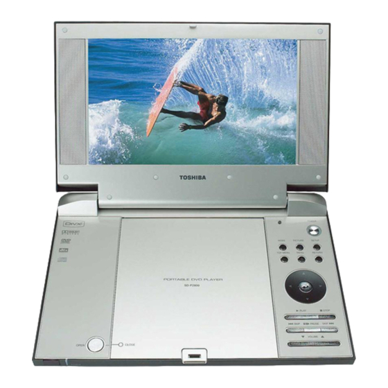
Summary of Contents for Toshiba SD-P2800SE
- Page 1 FILE No. 810-200595 REV: 01 SERVICE MANUAL PORTABLE DVD PLAYER SD-P2800SE Dec .,2005...
- Page 2 LASER BEAM CAUTION LABEL When the power supply is being turned on, you may not remove this laser cautions label. If it removes, radiation of laser may be received. PREPARATION OF SERVICING Pickup Head consists of a laser diode that is very susceptible to external static electricity. Although it operates properly after replacement, if it was subject to electrostatic discharge during replacement, its life might be shortened.
- Page 3 BATTERY LDVCC SPEAKER L/R BATTERY CD/DVD SW XS3/XS4 CDMD XS403 DVDMD TFT on/off JX100 CDLD DCLK DVDLD RFA5V FCS- TRK+ TRK- FCS+ XS402 JX101 LIMIT MECHANISM MAIN PCB OTHER 5V POWER SW KEY1 KEY2 DCLK JS201 Note: disconnect Inverter Harness JX102 KEY3 with marking.
- Page 4 T101 3.3V TFT 3.3V OVERALL BLOCK DIAGRAM HIGH VOLTAGE ASS’Y UPD5600 (T101) TFT MONITOR 27MHz VIDEO IN 64M SDRAM 74HC4053 HY57V641620ETP-H DVD 3.3V DVD 1.8V VIDEO OUT CARD SERVO & DVD PROCESSOR MPEG-2 DECODER Y/C OUT 74HC4053 & VIDEO ENCODER ZR36882 DV23 BA7660...
- Page 5 1. Troubleshooting 1. No power when turned on. 2. The initial screen is not displayed on the LCD. 3. The DVD drive does not work. 4. The operation of the DVD player stops at initializing display. 5. Image output stops during the operation. 6.
- Page 6 1.2 The initial screen is not displayed on the LCD. If the initial screen is not displayed on the LCD, check the following items. (1) Check the LED on the front If the LED does not light, proceed to 1.1. (2) Check the backlight If the backlight does not light up, separate the DVD player into top assembly and bottom assembly, and check the connector harness, and check the connectors for...
- Page 7 1.3 The DVD drive does not work. When the DVD drive does not work after the power is turned on, check the following items and repair or replace the defective parts. (1) Press the DISC cover switch and turn on the power. Then check whether or not the optical pick-up lens of the DVD drive lights.
- Page 8 1.5 Image output stops during the operation. If the image output from the media in the DVD player stops during the operation, replace the DVD drive. 1.6 No sound or abnormal sound comes out from the speakers in the DVD player. If no sound comes out from the speakers in the DVD player, check the following: (1) Check for moving images on the LCD screen Check whether or not the move of image stops in halfway.
- Page 9 MAIN BOARD CIRCUIT DIAGRAM (AUDIO CIRCUIT DIAGRAM) L510 CVBS L504 601H R489 C511 C589 150P 160P N406 C512 DVD 5V WM8728 ALRCLK FPCSTB(ML) LRCIN LATI2S JS502 AOUT0# I2CCLK(MC) SCKDSD L506 VD507 VD504 HSJ1594-010160 ABCLK I2CDAT(MD) BCKIN SDIDEM R481 601H STZ6.2N STZ6.2N AMCLK MCLK...
- Page 10 MAIN BOARD CIRCUIT DIAGRAM (CARD CIRCUIT DIAGRAM) DSPVCC33 DSPVCC33 JS508 R493 R492 SD_CD MEMDA[15:0] SD-CD1 SD-WP1 MEMDA4 MEMDA4-R DSPVCC33 XD18-VCC MEMDA3 MEMDA3-R MEMDA7-R XD17-DAT7 MEMDA5 MEMDA5-R MEMDA6-R CARD_SEL XD16-DAT6 C451 MEMDA2 MEMDA2-R MEMDA5-R XD15-DAT5 10uF/16V 0.1uF DAT0 RN205 300Rx 4 SDDAT1 SD8-DAT1 R480...
- Page 11 MAIN BOARD CIRCUIT DIAGRAM (DVD POWER & CHARGE CIRCUIT DIAGRAM) DCIN# TFT3V8 VD110 LM1117-1.8V L415 DVD1.8V 220U/16V 601H R281 DCIN# CB55 VD66 100N B240A C101 C402 C104 C108 C109 C110 C248 R255 10U/16V 10U/16V 100P C246 CB53 10U/16V 220N VD59 AO4801 VD44 pq033...
- Page 12 MAIN BOARD CIRCUIT DIAGRAM (FLASH & DAC & KEY CIRCUIT DIAGRAM) MEMAD[ 1 9:0] MEMAD15 MEMAD14 MEMAD13 MEMAD12 MEMAD11 MEMAD10 XS405 MEMDA[15:0] MEMAD9 FPL0.5B-SMT-45 MEMAD8 MEMAD16 MEMAD18 MEMAD17 MEMAD7 MEMAD6 MEMWR- MEMAD5 MEMAD4 MEMAD3 MEMAD15 MEMAD2 MEMAD14 MEMAD1 BYTE# VCCQ FLASH VCC MEMAD13 MEMAD12...
- Page 13 MAIN BOARD CIRCUIT DIAGRAM (MCU CIRCUIT DIAGRAM) TPA0172_MUTE CB75 C230 L201 100N BGH2012B601LT OTHER 5V CPU5V CB74 N202 100N CB61 24C04 100N N200 D1850 P4.2 PAUSE KEY1 P1.0/T2 P0.0 KEY2 P1.1/T2EX P0.1 KEY3 P1.2 P0.2 KEY4 DVD_RESET P1.3 P0.3 KEY5 TFT_RESET P1.4 P0.4...
- Page 14 MAIN BOARD CIRCUIT DIAGRAM (OPU CONNECTOR & DRIVER CIRCUIT DIAGRAM) DVD 5V L409 C431 C430 C432 C433 BGH2012B601LT 10u/16V 100P RF3V3 DVD 3V3 RF3V3 L410 BGH2012B601LT RFA5V L411 R436 BGH2012B601LT C428 47U/16V C434 470P L407 VD405 R437 220R DVD_LD 10uF/16V BGH2012B601LT KTA1298 C438...
- Page 15 MAIN BOARD CIRCUIT DIAGRAM (T101 CIRCUIT DIAGRAM) AVDD33 VDD33 VDD22 VDD22 601H CB62 CB99 601H 10u/16V 0.1uF 100P CON40 CB93 LCD_DIR_3V3 0.1uF CB87 100uF/16V 0.1uF VCLK VCLK VCLK DTMG 10u/16V SVD7 VDT7 SVD6 VDT6 DCR0/QE0 SVD5 VDT5 DCR1/QE1 SVD4 33*4 VDT4 DCR2/QE2 SVD3...
- Page 16 MAIN BOARD CIRCUIT DIAGRAM (TV TUNER & D TERMINAL & S-VIDEO CIRCUIT DIAGRAM) YUV-Y JS100 XDD-191-FK 601H 150P 160P TV100 VT2V8UP5510 VD116 DVD5V STZ6.2N 100UH CB97 100N JS507 10U/16V BA7660 D terminal 601H 220U/4V 160P 150P VD14 750K STZ6.2N ADDRESS 750K 601H 47U/4V...
- Page 17 MAIN BOARD CIRCUIT DIAGRAM (ZR36882 & SDRAM & FLASH CIRCUIT DIAGRAM) VDDPWM DVD3.3V TRACK_S R415 TRACK_S DVD1.8V SLED_S R404 C448 SLED_S SPINDLE_S R418 SPINDLE_PWM SPINDLE_S FOCUS_S R412 FOCUS_PWM C449 L412 L413 FOCUS_S 601H 601H C411 C414 C415 L414 C407 R398 601H 27nF 100K...
- Page 18 INVERTER BOARD CIRCUIT DIAGRAM BAV99 1.5A TFT ON/OFF BRIGHT CON 10U/16V 10U/16V 10U/16V 18P/3KV 820K 100N BHS-2P SST-CMP ISEN N001 N002 VSEN GDNA VDDA BAV99 470N 330P DRV2 DRV1 10U/16V 100K DTC144 RK7002 100N DCLK BRIGHT TFT-ON/OFF DCLK...
- Page 19 MAIN BOARD DIAGRAM (TOP)
- Page 20 MAIN BOARD DIAGRAM (BOTTOM)
- Page 21 INVERTER BOARD DIAGRAM...
- Page 22 SD-P2800 CHASSIS ASSEMBLY...
- Page 23 SD-P2800SE PACKING ASSEMBLY 43 44...
- Page 24 Note: The parts identified by mark are critical for safety. Replace only with part number specified. Note: Disconnect Inverter Harness(Loc.No.11) with marking. It may damage the LCD if Harness is not connected correctly. Loc.No. TOSHIBA Part No. Vender's Part No. Description AH301603 eb42180...
- Page 25 1 1, SHIBAURA 1 CHOME, MINATO KU, TOKYO 105 8001, JAPAN...


