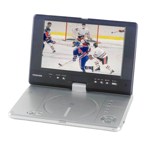
Summary of Contents for Toshiba SD-P2700-S-TN
-
Page 1: Portable Dvd Player
810-200507 FILE Rev.00 SERVICE MANUAL (TENTATIVE) PORTABLE DVD PLAYER VIDEO AUDIO SD-P2700-S-TN SD-P2700-S-TE SD-P2700-S-TR (SD-P2700-S-TN) Feb.,2005... -
Page 2: Preparation Of Servicing
LASER BEAM CAUTION LABEL When the power supply is being turned on, you may not remove this laser caution's label. If it was removed, the radiation of laser may be received. PREPARATION OF SERVICING Pickup Head consists of a laser diode that is very susceptible to external static electricity. Although it operates properly after the replacement, if it was subject to electrostatic discharge during replacement, the life of the product might be shortened. -
Page 3: Safty Precautions
SAFTY NOTICE SAFTY PRECAUTIONS LEAKAGE CURRENT CHECK Plug the AC line cord directly into 120V AC outlet (do Measure the AC voltage across the 1500 resistor. not use an isolation transformer for this check). Use an The test must be conducted with the AC switched on and AC voltmeter, having 5000 per volt or more sensitivity. - Page 4 KEY B PCB KEY A PCB PANEL3V3 PANEL3V3 JS506 JS507 VR500 LDVCC TXOUT- JS505 XS403 TXOUT+ JS508 TXOUT1- CD/DVD SW TFT LCD TXOUT1+ TXOUT2- TXOUT2+ SW401 TXCLKOUT- TXCLKOUT+ XS405 JS504 VRCD XS301 VRDVD DVDMD CDLD XS402 DVDLD AVCC XS401 FCS- TRK+ TRK- JS503...
-
Page 5: Overall Block Diagram
OVERALL BLOCK DIAGRAM KEY BOARD KEY BOARD LVDS OSCILLATOR TW8803 TFT MONITOR SDP2700KA DS90C383 OZ9RR SDP2700KB DC 12V 27MHz 16M FlashROM 64M SDRAM TC4W53 74HCU04 MX29LV160ABTC-70 NT56V6620COT-75S UB6220 SD CARD 27MHz RF AMP & SERVO & DVD PROCESSOR DV23(HD80) MPEG-2 DECODER & VIDEO ENCODER S-VIDEO OUT D TERMINAL PU mechanism... -
Page 6: Troubleshooting
1. Troubleshooting 1. No power when turned on. 2. The initial screen is not displayed on the LCD. 3. The DVD drive does not work. 4. The operation of the DVD player stops at initializing display. 5. Image output stops during the operation. 6. - Page 7 1.2 The initial screen is not displayed on the LCD. If the initial screen is not displayed on the LCD, check the following items. (1) Check the LED on the front If the LED does not light, proceed to 1.1. (2) Check the backlight If the backlight does not light up, separate the DVD player into the top assembly and the bottom assembly, and check the connector harness, and check the connectors for...
- Page 8 1.3 The DVD drive does not work. When the DVD drive does not work after the power is turned on, check the following items and repair or replace the defective parts. (1) Press the DISC cover switch at the center of the DVD player and turn on the power.
- Page 9 1.5 Image output stops during the operation. If the image output from the media in the DVD player stops during the operation, replace the DVD drive. 1.6 No sound or abnormal sound comes out from the speakers in the DVD player. If no sound comes out from the speakers in the DVD player, check the following: (1) Check for moving images on the LCD screen Check whether or not the move of image stops in halfway.
- Page 10 KEY BOARD CIRCUIT DIAGRAM XS302 DOWN FUN+ 12 HEADER PREW STOP TOP MENU R429 PAUS RETURN NEXT R430 PLAY MENU R431 D103 RIGHT R432 HS0038B FUN- SETUP LEFT...
- Page 11 MAIN BOARD CIRCUIT DIAGRAM (POWER CIRCUIT DIAGRAM) L101 CDRH6D38-330M C TFT HV VD013 cation: REPLACE PUSE WITH SAME TYPE AND RATING UDZ-174.7B VD009 C197 L106 UDZ-1715B C009 100N BGH2012B601LT R088 R038 16V/100U C077 DRVCC 5V T3A/125 V 16V/100U VD106 JS101 F101 FM 101 VD101...
- Page 12 MAIN BOARD CIRCUIT DIAGRAM (AUDIO CIRCUIT DIAGRAM) EM506 EM507 R515 C518 AUDIO OUT VD404 300P R514 N501A C509 R530 JS501 3.9K DVD AUX R513 4558 47U/4V C554 5.6K VD502 VD500 STZ6.2N STZ6.2N L-MAIN DVD 5V FMC3 R445 47U/4V R516 R517 100K C516 R529...
- Page 13 MAIN BOARD CIRCUIT DIAGRAM (MPEG CIRCUIT DIAGRAM) DVD 3.3V CB113 CB147 CB121 CB126 CB31 CB31 CB31 CB31 L418 0.1uF 0.1uF 0.1uF 0.1uF 0.1uF 0.1uF 0.1uF 0.1uF BGH2012B601LT R444 DV33 DVD 5V DVD 3.3V DVD 5V DV33 L412 R496 SPDIT OUT BGH2012B601LT R494 G402...
- Page 14 MAIN BOARD CIRCUIT DIAGRAM (SD CARD CIRCUIT DIAGRAM) R627 R626 R628 R625 R624 R623 R622 R600 NC AVCC R602 R601 R603 NC R616 33 R617 10 C618 R618 33 R619 10 100N R620 390 N602 USB6220 CHIP G600 R621 $$$283 R604 C600 N601...
- Page 15 MAIN BOARD CIRCUIT DIAGRAM (TFT CIRCUIT DIAGRAM) R353 TFT3.3V 27MHZ N308 N309 VSYN TC7S08 C365 R331 100N REST CLR- SN74HC174 R353 C300 R307 100P R359 33 TW VDD R308 33 R309 33 RN302 L304 CLOCK C323 BGH2012B601LT 100N CNTRL PLLGND TFT 3.3V ENABLE PLLGND...
- Page 16 HV BOARD CIRCUIT DIAGRAM 1210 UI8.5 SOT-23 SOT-23...
- Page 17 SD-P2700KA KEY PCB BOARD DIAGRAM SD-P2700 BATTERY PROTECTOR PCB BOARD DIAGRAM SD-P2700 BATTERY IF PCB BOARD DIAGRAM SD-P2700KB KEY PCB BOARD DIAGRAM SD-P2700 HV PCB BOARD DIAGRAM...
- Page 18 MAIN PCB BOARD DIAGRAM(TOP)
- Page 19 MAIN PCB BOARD DIAGRAM(BOTTOM)
- Page 20 SD-P2700 PACKING ASSEMBLY...
- Page 21 SD-P2700 CHASSIS ASSEMBLY...
-
Page 22: Parts List
PARTS LIST Loc No. TOSHIBA Part No. Vender's Part No. Description AH301040 b32298d function button AH300840 21611 key A(function switch) PCB AH301041 b32292 LCD mask AH301037 b32318 insert nut AH301043 b32327 speaker bracket AH301074 b32303 speaker net left AH301075 b32304... - Page 23 Loc No. TOSHIBA Part No. Vender's Part No. Description 26/27 AH300828 21583 main PCB & battery connecter AH300854 s8115a DVD drive assy AH300691 a2964 screw M2*3 AH300692 a2663a screw M2*4 AH301017 a2912 screw M2*5 AH301062 a2673 screw M3*4 AH301063 a2669 screw M2.5*6...


