Sign In
Upload
Manuals
Brands
Toshiba Manuals
Industrial Electrical
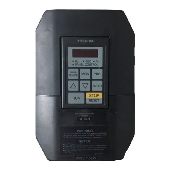
tosvert VF-SXN
Toshiba tosvert VF-SXN Manuals
Manuals and User Guides for Toshiba tosvert VF-SXN. We have
1
Toshiba tosvert VF-SXN manual available for free PDF download: Instruction Manual
Toshiba tosvert VF-SXN Instruction Manual (115 pages)
Three Phase 400V 1.5-15 kW Compact Inverter
Brand:
Toshiba
| Category:
Industrial Electrical
| Size: 4.7 MB
Table of Contents
Safety Notices
2
Introduction
3
Contents
4
Inspection and Cautions at Delivery
7
Cautions for Installation
9
External View and Names of each Part
11
How to Remove the Operation Panel
13
Cautions for Application
15
Cautions Regarding Motor
16
Cautions Regarding the Inverter
17
Wiring Precautions
18
Wiring to the Inverter
19
Installation of the Molded Case Circuit Breaker
20
Installation of the Primary Magnetic Contactor
21
Explanation of Leakage Current
21
Installation of the Secondary Magnetic Contactor
22
Installation of an Overload Relay
22
Explanation of the Power Factor Improvement Capacitor
22
Explanation of Radio Wave Obstruction
22
Installation of an Input Reactor
23
Selection Examples of Wiring Equipment
23
Standard Connection
25
Examples of Standard Wiring
26
For Three Phase Input
26
Terminal Functions
29
Control Circuit Terminals
29
Main Circuit Terminals
29
Operation and Adjustment
31
Operation Panel
32
Basic Operation
33
Operation and Stop with the Panel
33
Changing the Frequency During Operation
33
Setting and Adjusting Functions
34
Group Categories
34
Display Modes
36
Drive Mode
36
Setting Function of the Frequency Command Value
36
Status Warning
37
Trip Information
37
Monitoring Mode
39
Monitor Operation Examples in the Drive Mode
39
Programming Mode
40
Parameter Settings and Display Function
40
Programming Mode and Adjustment Function
41
FM Adjustment Example
41
Set Value Warning Displays
42
Jogging Mode
43
Command Mode Selection
44
Switching of Panel/Remote Control
44
RUN/STOP Command
44
Function for Setting Frequency Command Value
44
Function for Setting Parameters
45
Setting of Standard Parameter Groups
45
Standard Setting Pattern
46
Output Frequency
46
Selection of Stopping Method Using Panel
47
Error Reset
48
To Reset from the Panel
48
Various Operation Functions
49
Permissible Maximum Frequency
50
Setting of Voltage and Frequency Characteristics
51
Maximum Frequency
51
Torque Boost
51
Setting to Increase the Start-Up Torque
51
Automatic Torque Boost
52
No-Load Current Setting
52
Torque Boost Maximum Value Setting
52
Base Frequency
53
V/F Pattern
53
Example of Base Frequency Setting
53
V/F Pattern Setting
53
Acceleration and Deceleration Times
54
Acceleration/Deceleration Pattern
54
S-Character 1 Deceleration Pattern
55
Forward Run, Reverse Run, Coasting Stop and Emergency Stop
56
Automatic Changeover of the Acceleration/Deceleration Time
56
Operation with the Panel
56
Operation with External Signals
57
Example of Forward/Reverse Run
57
Terminal Input and Operations
58
Emergency Stop
58
Frequency Setting Signals
59
Types of Emergency Stop and Operations
59
Types of Frequency Setting Signals
59
RR Terminal Input Priority
59
Frequency Setting Signal
61
RR Terminal Frequency Setting Signal Characteristics
61
Adjustment of the RR Analog Terminal Input
61
Adjustment of the RR Input Terminal Gain
61
Frequency Setting Signal Characteristics
62
Upper Limit Frequency and Lower Limit Frequency
63
Jogging Run
63
Upper Limit Frequencies
63
Lower Limit Frequencies
63
Connection of Jog Switch
64
Example of Operation with JOG Switch
65
Multispeed Run
66
Example of Multispeed Run
67
Connection of the Terminals for Multispeed Run Signals
67
Frequency Jump
68
Start-Up Frequency
69
Operation Starting Frequency
69
DC Injection Braking
70
Example of DC Injection Braking Operation
70
Regenerative Discharge Brake
71
Setting and Display of Universal Unit Multiplication Factor
72
PWM Carrier Frequency Changeover
72
Output Voltage Reduction, Power Voltage Compensation
73
Slip Frequency Compensation
74
Motor Rating Slip Frequency
74
Signals and Connection for Automatic Operation Control
75
Connection of Signals
76
Operation Signals
76
Terminal Selection
76
Input Terminal
76
Output Terminal Selection
77
Selection of Input Terminals and Operation Frequencies
77
Upper Limit/Lower Limit Frequency Signal Output
79
Low Speed Signal Output, Speed Reached Signal Output
79
Speed Reached Signal Output
80
Connectable Meters
81
Connection of the Frequency Meter
81
Connection of Ammeter
81
Connection of Fault Detection Signal
82
Terminals for the Fault Detection Signal
82
Protective Functions
83
Electronic Thermal Function
84
Stall Prevention Function
84
Electronic Thermal Operation Characteristics
84
Electronic Thermal Characteristics Selection
85
Retention of Trip
86
Retry Function
86
Power Control Function
87
Fault Indication and Retry Process
87
Machine Specifications
88
Machine Type and Main Standard Specifications
89
External Dimensions
91
External Installation of Table
92
External Dimensions and Weight
92
Options
93
Input Reactor
94
Model, Rating and Dimensions
94
Radio Noise Reduction Filter
95
Braking Resistor
95
Outline Drawing
95
Wiring Diagram
95
Operation Panel Extension Cable
96
Error Displays, Contents and Remedies
97
Inverter Trip Causes and Remedies
98
Other Error Symptoms
100
Maintenance and Inspection
102
Preventative Maintenance and Periodic Inspection
103
Inspection Places
103
Pressure Resistance Test
103
Voltage and Temperature Test
103
Storage
104
Table of Parameters
107
Input Terminal Information
113
Output Terminal Information
113
Character Code
114
Advertisement
Advertisement
Related Products
Toshiba TOSVERT-130P2
Toshiba TOSVERTVF-PS1
Toshiba Tosvert-130
Toshiba TOSVERT-130G2+
Toshiba TOSVERT BCN001Z
Toshiba TOSVERT VF Series
Toshiba TOSVERT-300MVi
Toshiba TOSVERT-130H
Toshiba TOSVERT-130H1
Toshiba TOSVERT VF-AS
Toshiba Categories
Laptop
Air Conditioner
TV
LCD TV
All in One Printer
More Toshiba Manuals
Login
Sign In
OR
Sign in with Facebook
Sign in with Google
Upload manual
Upload from disk
Upload from URL