Sign In
Upload
Manuals
Brands
Toshiba Manuals
Inverter
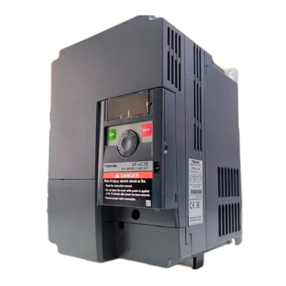
TOSVERT VF-nC3E
Toshiba TOSVERT VF-nC3E Manuals
Manuals and User Guides for Toshiba TOSVERT VF-nC3E. We have
1
Toshiba TOSVERT VF-nC3E manual available for free PDF download: Instruction Manual
Toshiba TOSVERT VF-nC3E Instruction Manual (253 pages)
Industrial Inverter (For 3-phase induction motors)
Brand:
Toshiba
| Category:
Inverter
| Size: 4.39 MB
Table of Contents
Explanation of Markings
2
Meanings of Symbols
2
Safety Precautions
2
Safety Precautions (Limits in Purpose)
3
General Operation
4
Transportation & Installation
5
Wiring
6
Operations
7
Maintenance and Inspection
8
When Operation by Using Remote Keypad Is Selected
8
When Retry Function Is Selected
8
When Sequence for Restart after a Momentary Failure Is Selected
8
Attach Caution Labels
9
Disposal
9
Introduction
10
Table of Contents
11
Check Product Purchase
14
1 Read First
14
Contents of the Product
15
Explanation of the Name Plate Label
15
Names and Functions
16
Outside View
16
Bottom View
16
Front View
16
Example of the Label
17
Opening the Cover
17
About the Monitor Display
17
LED Display (Numbers)
17
With Cover Open
18
Opening the Terminal Cover
19
Removing the Power Terminal Cover
19
Power Circuit and Control Circuit Terminal Boards
22
Power Circuit Terminal Board
22
Control Circuit Terminal Board
25
Wire Size
25
Recommended Ferrule
25
Notes on the Application
26
Motors
26
Comparisons with Commercial Power Operation
26
Operation in the Low-Speed Area
26
Low Loads and Low Inertia Loads
27
Occurrence of Instability
27
Braking a Motor When Cutting off Power Supply
27
Load that Produces Regenerative Torque
27
Motors with a Brake
28
Inverters
28
Protecting Inverters from Overcurrent
28
Inverter Capacity
28
Power Factor Correction Capacitor
29
Operating at Other than Rated Voltage
29
If Power Supply Distortion Is Not Negligible
29
What to Do about the Leakage Current
30
Leakage Current from the Inverter Main Unit
30
Influence of Leakage Current Across Ground
30
Leakage Current Path Across Ground
30
Influence of Leakage Current Across Lines
31
Thermal Relays
31
Remedies
31
Installation
32
Installation Environment
32
CT and Ammeter
32
How to Install
34
Normal Installation
34
Side-By-Side Installation
34
Calorific Values of the Inverter and the Required Ventilation
35
Panel Designing Taking into Consideration the Effects of Noise
36
Installing more than One Unit in a Cabinet
36
2 Connection
37
Cautions on Wiring
37
Preventing Radio Noise
38
Control and Main Power Supply
38
Standard Connections
39
Standard Connection Diagram 1
40
Standard Connection Diagram - SINK (Negative) (Common:CC)
40
Standard Connection Diagram 2
41
Description of Terminals
42
Power Circuit Terminals
42
Power Supply and Motor Connections
42
Connections with Peripheral Equipment
42
Control Circuit Terminals
43
Power Circuit
43
Connection of SINK (Negative) Logic/Source (Positive) Logic
46
Examples of Connections When an External Power Supply Is Used
47
Sink (Negative) Logic
47
Source (Positive) Logic
47
3 Operations
49
Simplified Operation of the VF-Nc3E
50
Parameter Setting
50
How to Run and Stop
51
Run and Stop Using the Panel Keypad
51
How to Set the Frequency
52
Coast Stop
52
Setting Using the Keypad
52
Setting of Frequency Using External Signals to Terminal Block
54
Frequency Setting
54
Setting the Frequency Using External Potentiometer
54
Setting the Frequency Using Voltage Input (0-10V)
54
How to Operate the VF-Nc3E
55
Parameter Setting (Default Setting)
55
Meter Setting and Adjustment
59
Meter Selection
59
Meter Adjustment Gain
59
Resolution
60
Internal Calculated Value
60
Frequency Meter
60
Ammeter
60
Adjusting the Meter in Inverter Stop State
61
Adjustment of Output Current
61
Other Adjustments
61
Setting the Electronic Thermal
62
Motor Electronic-Thermal Protection Level 1
62
Motor Electronic-Thermal Protection Level 2
62
Electronic-Thermal Memory
62
Setting the Electronic Thermal
63
Output Current Reduction Factor
64
Using a VF Motor (Motor for Use with Inverter)
64
Motor 150%-Overload Time
65
Inverter Overload Characteristics
65
Inverter Overload Protection Characteristic
65
Electronic Thermal Memory
66
Preset-Speed Operation (Speeds in 15 Steps)
67
Preset-Speed Frequency
67
Preset-Speed Frequency Setting
67
Example of a Connection Diagram
68
Using Other Speed Commands with Preset-Speed Command
69
4 Setting Parameters
70
Setting Parameters
70
Setting and Display Modes
70
Standard Monitor Mode
70
Setting Monitor Mode
70
Status Monitor Mode
71
How to Set Parameters
72
Easy Setting Mode
72
Standard Setting Mode
73
Basic Parameters
73
Extended Parameters
73
Settings in the Easy Setting Mode
74
Easy Setting Mode (Default Registered Parameters)
74
Setting Parameters in the Easy Setting Mode
74
Settings in the Standard Setting Mode
75
How to Set Basic Parameters
75
How to Set Extended Parameters
76
Adjustment Range and Display of Parameters
76
Changed Parameters History Search (History Function)
76
Set Parameters by Purpose (Guidance Function)
76
Functions Useful in Searching for a Parameter or Changing a Parameter Setting
76
Reset Parameters to Default Settings
77
Call Saved Customer Settings
77
Search Changed Parameters
77
Automatic Edit Function
77
How to Search and Reprogram Parameters
78
Return to Default Settings
79
Default Setting
79
Programmed Value
79
Trip Record Clear
80
Cumulative Operation Time Clear
80
Initialization of Type Information
80
Save User Setting Parameters
80
EASY Key Function
81
Registered Parameters Display Selection
81
Easy Setting Mode Parameter
81
How to Select Parameters
82
5 Main Parameters
83
Searching for Changes Using the History Function
83
History Function
83
How to Use the History Function
83
Setting a Parameter Using the Guidance Function
84
Guidance Function
84
How to Use the Guidance Function
85
Setting Acceleration/Deceleration Time
87
Automatic Acceleration/Deceleration
87
Methods of Setting Automatic Acceleration/Deceleration
88
Manually Setting Acceleration/Deceleration Time
88
Increasing Starting Torque
89
Torque Boost Setting Macro Function
89
Increasing Torque Automatically According to the Load
89
Energy-Saving Operation
90
Increasing Torque Manually (V/F Constant Control)
91
Set V/F Control Mode Selection
91
Selection of Operation Mode
92
Command Mode Selection
92
Frequency Setting Mode Selection
92
Preset-Speed Operation
93
Input Terminal Settings
93
Example of Run and Frequency Command Switching
94
Command Mode and Frequency Setting Mode Switching
94
Forward/Reverse Run Selection (Panel Keypad)
95
Meter Setting and Adjustment
95
Maximum Frequency
96
Upper Limit and Lower Limit Frequencies
97
Base Frequency
98
Base Frequency Voltage
98
Selecting Control Mode
99
V/F Control Mode Selection
99
Setting V/F Control Mode Selection to 3
100
Constant Torque Characteristics
100
Setting for Fans and Pumps
101
Motor Constant Must be Set
102
Vector Control
102
Manual Torque Boost - Increasing Torque Boost at Low Speeds
105
Preset-Speed Operation (Speeds in 15 Steps
106
Standard Default Setting
106
Setting the Electronic Thermal
106
Registered Parameters Display Selection
106
6 Other Parameters
107
Input/Output Parameters
107
Low-Speed Signal
107
Output of Designated Frequency Reach Signal
108
Speed Reach Detection Band
108
Parameter Setting of Designated Frequency and Detection Band
108
Parameter Setting of Output Terminal Selection
108
Output of Set Frequency Speed Reach Signal
109
Speed Reach Setting Frequency
109
Input Signal Selection
110
Priority Selection (both F and R Are ON)
110
Changing the Functions of VI Terminal
112
Analog/Logic Input Selection (VI Terminal)
112
Terminal Function Selection
113
Changing Control Logic Switching
113
Keeping an Input Terminal Function Always Active (ON)
113
Sink/Source Switching
113
Modifying Input Terminal Functions
114
Modifying Output Terminal Functions
114
Basic Parameters 2
115
Switching Motor Characteristics Via Terminal Input
115
Setting of Switching Terminals
116
Example of Setting a Terminal for Switching : Sink Logic
116
V/F 5-Point Setting
117
Setting Frequency Command
117
Switching Frequency Command
117
Setting Frequency Command Characteristics
118
VI Input Point 1 Setting
118
VI Input Point 1 Frequency
118
0-10Vdc Voltage Input Adjustment
119
4-20Madc Current Input Adjustment
119
0-5 VDC Voltage Input, or Used to Adjust External Volume
119
Setting of Frequency with the Input from an External Logic
120
External Logic Input - up Response Time
120
External Logic Input - up Frequency Steps
120
External Logic Input - down Response Time
120
Adjustment with Continuous Signals
121
Adjustment with Pulse Signals
121
Sample Sequence Diagram 2: Adjustment with Pulse Signals
122
If Two Signals Are Impressed Simultaneously
122
About the Setting of the Initial Up/Down Frequency
122
About the Change of the Initial Up/Down Frequency
122
Fine Adjustment of Frequency Setting Signal
123
VI Voltage Bias
123
VI Voltage Gain
123
Bias Adjustment of VI Input Terminal ( F470 )
123
Operation Frequency
124
Starting Frequency
124
Starting Frequency Setting
124
Run/Stop Control with Frequency Setting Signals
124
DC Braking
125
DC Braking Starting Frequency
125
DC Braking Current
125
DC Braking Time
125
Time Limit for Lower-Limit Frequency Operation
126
Output Frequency [Hz]
126
Jump Frequency - Avoiding Frequency Resonance
127
Jumping Width
127
Preset-Speed Frequencies
127
PWM Carrier Frequency
128
Random Mode
128
Carrier Frequency Control Mode Selection
128
Trip-Less Intensification
130
Auto-Restart (Restart of Coasting Motor)
130
Auto-Restart Control Selection
130
Restarting Motor During Coasting
131
Motor Speed Search at Starting
131
Application to a Crane or Hoist
131
Regenerative Power Ride-Through Control
132
If Momentary Power Failure Occurs
133
An Example of Setting When F302=2
133
Retry Function
134
Retry Selection (Number of Times)
134
Dynamic (Regenerative) Braking - for Abrupt Motor Stop
135
Dynamic Braking Selection
135
Dynamic Braking Resistance
135
Dynamic Braking Resistor Capacity
135
Connecting an External Braking Resistor
136
Separate-Optional Resistor (with Thermal Fuse)
136
Connecting Thermal Relays and an External Braking Resistor
136
Optional Dynamic Braking Resistors
138
Minimum Resistances of Connectable Braking Resistors
138
Avoiding Overvoltage Tripping
139
Overvoltage Limit Operation
139
Over-Voltage Stall Protection Level
139
Overvoltage Limit Operation Level
139
Output Voltage Adjustment/Supply Voltage Correction
140
Supply Voltage Correction
140
No Voltage Compensation/Output Voltage Limited
141
Voltage Compensation/Output Voltage Limited
141
No Voltage Compensation/No Output Voltage Limit
141
Voltage Compensation/No Output Voltage Control
141
Braking Function
142
Brake Sequence Control
142
Creeping Time
142
Braking Mode Selection
142
PID Control
143
PID Control Waiting Time
143
Proportional Gain
143
Integral Gain
143
External Connection
144
Types of PID Control Interfaces
144
Setting PID Control
145
Adjusting the PID Control Gain Level
145
P-Gain Adjustment Parameter
145
I-Gain Adjustment Parameter
145
D-Gain Adjustment Parameter
146
Previous Deviation-Current Deviation
146
Adjusting Feedback Inpu
146
Setting the Time Elapsed before PID Control Starts
147
PID Control Forward/Reverse Characteristic Switch
147
Setting Motor Constants
148
Auto-Tuning
148
Motor Rated Current
148
Motor No-Load Current
148
Setting Vector Control and Auto-Tuning Independently
149
Precautions on Auto-Tuning
149
Setting Vector Control and Manual Tuning Independently
149
Setting Procedure Adjust the Following Parameters
150
Adjustment Method for the Moment of Inertia of the Load
150
2Nd Acceleration/Deceleration
151
Switching Acceleration/Deceleration Time 1 & 2
151
Switching According to Terminal
152
Acceleration/Deceleration Pattern Setting
152
Parameter Configuration Method
152
Linear Acceleration/Deceleration
153
S-Pattern Acceleration/Deceleration 1
153
S-Pattern Acceleration/Deceleration
153
Protection Functions
154
Setting Motor Electronic Thermal Protection
154
Setting of Stall Prevention Level
154
Inverter Trip Retention
155
Inverter Trip Retention Selection
155
Display During Operation of the Stall Prevention
155
Emergency Stop
156
Emergency Stop Selection
156
Emergency Stop from Terminal
156
Output Phase Failure Detection
157
Emergency Stopping from the Operation Panel
157
Input Phase Failure Detection
158
Input Phase Failure Detection Selection
158
Control Mode for Small Current
158
Small Current Detection Hysteresis
158
Example of Operation
159
Output Terminal Function: 26 (UC) Low Current Detection
159
Detection of Output Short-Circuit
159
Detection of Output Short-Circuit at Start-Up
159
Over-Torque Trip
160
Over-Torque Trip/Alarm Selection
160
Over-Torque Detection Level
160
Over-Torque Detection Time
160
Output Terminal Function: 28 (OT) Over-Torque Detection
161
Cooling Fan Control Selection
161
Cooling Fan ON/OFF Control
161
Cumulative Operation Time Alarm Setting
162
Undervoltage Trip
162
Undervoltage Trip/Alarm Selection
162
VI Analog Input Break Detection
163
Parts Replacement Alarms
163
VI Analog Input Break Detection Level
163
Number of Starting Alarm
164
Adjustment Parameters
165
Pulse Train Output for Meters
165
Logic Output/Pulse Train Output Selection (OUT)
165
Pulse Train Output Function Selection (OUT)
165
Calibration of Analog Output
166
Analog Output Signal Selection
166
Inclination Characteristic of Analog Output
166
Analog Output Bias
166
Operation Panel Parameter
167
Prohibition of Key Operations and Parameter Settings
167
Password Setup Method
168
Password Examination Method
168
Prohibit Changing Parameter Settings with Logic Input
169
Current/Voltage Unit Selection
170
Example of Setting
170
Display in Percentage Terms
170
Display in Amperes/Volts
170
Displaying the Motor or the Line Speed
171
Free Unit Display Scale
171
Displaying the Motor Speed
171
Displaying the Speed of the Loading Unit
171
Changing the Steps in Which the Value Increment
172
Changing the Initial Display of the Panel
173
Initial Panel Display Selection
173
Initial Extension Panel Display Selection
173
Changing the Display Format While Power Is on
173
Parameter Registration to Easy Setting Mode
174
Communication Function (RS485)
174
Communication Function Settings
177
Transmission Specifications
177
Configuration of RS485 Connector and Wiring
178
Connection Example When Using the Computer Link Function
179
Independent Communication
179
Broadcast Communication
180
Free Notes
180
7 Operations with External Signal
181
Check External Signal Conditions
181
Applied Operations by an I/O Signal (Operation from the Terminal Block
182
Input Terminal Function
182
Settings for the Logic Input Terminal Function
182
About Programmable Controllers and Interfaces
183
3-Wire Operation
184
Jog Run
185
List of Logic Input Terminal Function Settings
186
Assign One Type of Function to an Output Terminal
187
Control Terminal Block
187
Output Terminal Function (Sink Logic)
187
Assign Two Types of Functions to the Output Terminal (OUT)
188
Timing Chart
188
List of Detection Levels for Output Terminal Selection
189
List of Output Terminal Function Settings
189
Analog Input Terminal (VI) Function Settings
190
Speed Instruction (Analog Signal) Settings from External Devices
190
Settings Depending on Voltage (0 to 10 V) Input
191
Settings Depending on Current (4 to 20 Ma) Input
192
Settings Depending on Voltage (0 to 5 V) Input
193
8 Monitoring the Inverter Status in Operation / before Tripping
194
Flow of Status Monitor Mode
194
Status Monitor under Normal Conditions
195
Display of Trip Information
199
Trip Code Display
199
Display of Trip Information at the Occurrence of a Trip
199
Example of Call-Up of Trip Information
199
9 Peripheral Devices
203
Selection of Wiring Materials and Devices
203
Selection of Cable Size
203
Selection of Wiring Devices
204
Installation of a Magnetic Contactor
205
Magnetic Contactor in the Primary Circuit
205
Notes on Wiring
205
Example of Connection of a Magnetic Contactor in the Primary Circuit
205
Installation of an Overload Relay
206
Magnetic Contactor in the Secondary Circuit
206
Optional External Devices
207
10 Table of Parameters and Data
208
Frequency Setting Parameter
208
Basic Parameters
208
Extended Parameters
211
Default Settings by Inverter Rating
223
Input Terminal Function
224
Output Terminal Function
227
11 Specifications
229
Models and Their Standard Specifications
229
Common Specification
230
Outside Dimensions and Mass
232
Outline Drawing
233
12 Before Contacting Your Toshiba Distributor - Trip Information and Remedies
234
Trip Causes/Warnings and Remedies
234
Restoring the Inverter from a Trip
239
If the Motor Does Not Run While no Trip Message Is Displayed
240
How to Determine the Causes of Other Problems
241
13 Inspection and Maintenance
242
Regular Inspection
242
Periodical Inspection
243
Check Points
243
Cautions about Cleaning
243
Replacement of Expendable Parts
245
Cooling Fan Inspection
245
Smoothing Aluminum Electrolytic Capacitor Inspection
245
Estimated Time of Replacement of the Other Principal Parts
246
Contacting with Your Toshiba Distributor
246
Keeping the Inverter in Storage
247
Storage Location
247
Periodical Check
247
14 Warranty
248
15 Disposal of the Inverter
249
16 Appendix
250
How to Cope with the CE Directive
250
About the Low-Voltage Directive
251
Measures to Satisfy the Low-Voltage Directive
251
EMC Standards
251
Advertisement
Advertisement
Related Products
Toshiba VF-NC3C
Toshiba VFNC3-2001P
Toshiba VFNC3-2007P
Toshiba VFNC3-2015P
Toshiba VFNC3-2037P
Toshiba VFNC3S-1001P
Toshiba VFNC3S-1007P
Toshiba VFNC3S-2015PL
Toshiba VFNC3S-2022PL
Toshiba TOSVERT VFNC1S-1001P
Toshiba Categories
Laptop
Air Conditioner
TV
LCD TV
All in One Printer
More Toshiba Manuals
Login
Sign In
OR
Sign in with Facebook
Sign in with Google
Upload manual
Upload from disk
Upload from URL