Sign In
Upload
Manuals
Brands
Toshiba Manuals
Laptop
Tecra M10
User Manuals: Toshiba Tecra M10 14.1-inch Laptop
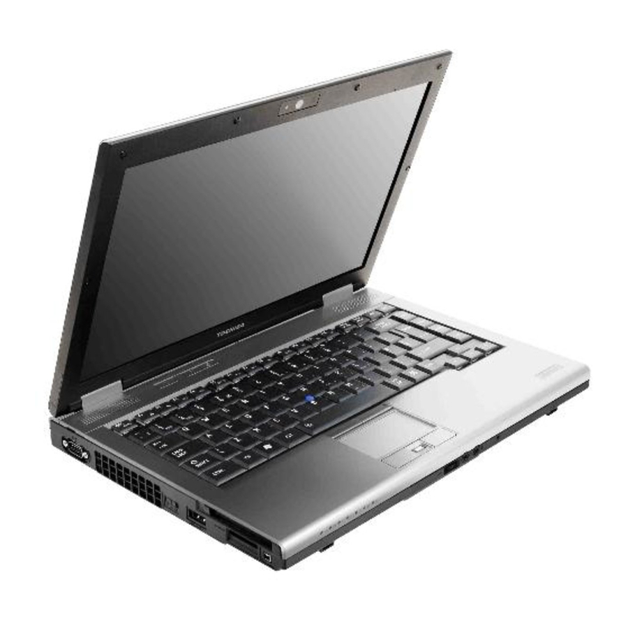
Manuals and User Guides for Toshiba Tecra M10 14.1-inch Laptop. We have
6
Toshiba Tecra M10 14.1-inch Laptop manuals available for free PDF download: Maintenance Manual, User Manual, Specifications, Specification Sheet
Toshiba Tecra M10 Maintenance Manual (475 pages)
Brand:
Toshiba
| Category:
Laptop
| Size: 9.12 MB
Table of Contents
Safety Precautions
3
Table of Contents
6
Chapter 1 Hardware Overview
11
Hardware Overview
13
Features ...................................................................................................................... 1-1
13
System Unit Block Diagram ...................................................................................... 1-9
13
Inch Floppy Disk Drive (USB External) ........................................................... 1-15
13
Inch Hard Disk Drive......................................................................................... 1-16
13
Optical Drive (ODD) ............................................................................................... 1-18
13
Keyboard................................................................................................................. 1- 22
13
TFT Color Display.................................................................................................. 1- 23
13
Power Supply .......................................................................................................... 1- 26
13
Batteries .................................................................................................................. 1- 28
13
Features
15
Microprocessor
15
Memory
15
Chipset
15
Keyboard
16
TOSHIBA Dual Pointing Device
16
Universal Serial Bus (USB2.0)
17
Esata/Usb Combo
17
External Monitor (RGB) Port
17
Battery Pack
17
Expresscard Slot(Not Used)
18
Smartcard Slot
18
Fingerprint Sensor
18
Docking Interface Port
18
Internal Modem
19
Internal LAN
19
Wireless LAN
19
Web Camera
19
TOSHIBA Presentation Button
20
TOSHIBA Assist Button
20
Figure 1-1 Front of the Computer
21
Figure 1-2 System Unit Configuration
22
System Unit Block Diagram
23
Figure 1-3 System Unit Block Diagram
23
BIOS ROM (Flash Memory)
24
3.5-Inch FDD Specifications
29
3.5-Inch Floppy Disk Drive (USB External)
29
Figure 1-4 3.5-Inch FDD (USB External)
29
2.5-Inch Hard Disk Drive
30
Figure 1-5 2.5-Inch HDD
30
DVD-ROM Drive
32
Optical Drive (ODD)
32
DVD-ROM & CD-R/RW Drive Specifications
33
Figure 1-6 DVD Super Multi Drive
34
DVD Super Multi Drive Outline Dimensions
35
TFT Color Display
37
Figure 1-8 LCD Module
37
FL Inverter Board Specifications
39
Power Supply
40
Power Supply Output Rating
41
Battery Specifications
42
Main Battery
42
Battery Charging Control
43
Time Required for Charges
43
Data Preservation Time
44
RTC Battery
44
RTC Battery Charging/Data Preservation Time
44
AC Adapter
45
AC Adapter Specifications
45
Chapter 2 Troubleshooting Procedures
47
Tables
51
Figures
51
Table
51
Troubleshooting
53
Troubleshooting Flowchart
55
Power Supply Troubleshooting
60
Power Status Check
60
Battery Icon
60
DC in Icon
61
Error Code Check
62
Error Code
63
DC Power Supply (AC Adapter)
63
2Nd Battery
64
S3V Output
64
E5V Output
64
Connection Check
68
Charging Check
68
Replacement Check
69
System Board Troubleshooting
70
Message Check
71
Serial Port Check or Debugging Port Check
73
A Set of Tool for Debug Port Test
73
Debug Port Error Status
75
Diagnostic Test Program Execution Check
84
USB FDD Troubleshooting
85
FDD Head Cleaning Check
85
FDD Error Code and Status
86
Connector Check and Replacement Check
87
2.5” HDD Troubleshooting
89
Partition Check
89
Hard Disk Drive Error Code and Status
92
Keyboard Troubleshooting
94
Touch Pad Troubleshooting
96
Display Troubleshooting
98
External Monitor Check
98
Optical Disk Drive Troubleshooting
101
Modem Troubleshooting
103
LAN Troubleshooting
105
Wireless LAN Troubleshooting
106
Transmitting-Receiving Check
106
Antennas' Connection Check
107
Bluetooth Troubleshooting
109
Sound Troubleshooting
111
Bridge Media Slot Troubleshooting
113
Check on Windows os
113
PCI Expresscard Slot Troubleshooting
114
Gigabit Ether Expresscard
114
USB2.0 5In1 Expresscard
114
Fingerprint Sensor Troubleshooting
115
Setting Windows Log-ON Password
116
Registration of Fingerprint
116
Authentication of Fingerprint
117
Web Camera Troubleshooting
119
Intel Turbo Memory Troubleshooting
121
Chapter 3 Tests and Diagnostics
123
The Diagnostic Test
129
Executing the Diagnostic Test
132
Diagnostics Menu (T&D)
133
H/W Initial Information Setting Tool
136
Heatrun Test Program
136
Setting of the Hardware Configuration
137
Initial Configuration
137
DMI Information Save
138
DMI Information Recovery
138
Heatrun Test
139
Subtest Names
140
System Test
142
ROM Checksum
142
Fan ON/OFF
142
Geyserville
142
Quick Charge
143
DMI Read
143
Memory Test
144
Conventional Memory
144
Protected Mode
144
Cache Memory (On/Off)
144
Keyboard Test
145
Pressed Key Code Display
145
Display Test
146
VRAM Read/Write for VGA
146
Gradation for VGA
146
Gradation for LCD
146
Gradation & Mode Test for VGA
147
All Dot On/Off for LCD
147
“H” Pattern Display
148
LCD Brightness
148
LCD EDID Information
148
Floppy Disk Test
149
Sequential Read
150
Sequential Read/Write
150
Random Address/Data
150
Write Specified Address
150
Printer Test
151
Ripple Pattern
151
Async Test
153
FIR/SIR Point to Point (Send)
153
FIR/SIR Point to Point (Receive)
153
Wraparound (Board)
153
Hard Disk Test
154
Cross Talk & Peak Shift
156
Partial Read
156
Read Specified Address
156
W-R-C Specified Address
156
Real Timer Test
157
Backup Memory
157
Real Time Carry
158
NDP Test
159
Expansion Test
160
PCMCIA Wraparound
160
RGB Monitor ID
161
CD-ROM/DVD-ROM Test
162
Error Code and Error Status Names
163
Hard Disk Test Detail Status
166
HDC Error Register Contents
167
Only One Test
168
Program Description
168
Pressed Key Display (Main Key)
169
Touch Pad
170
Wireless Communication Switch
171
Usb
171
Acceleration Sensor
174
Docker Dock/Undock
176
Fan Control
176
Head Cleaning
177
Log Utilities
178
Running Test
180
Floppy Disk Drive Utilities
181
FORMAT Program
182
COPY Program
183
DUMP Program
184
HDD ID READ Program
185
System Configuration
186
Wireless LAN Test Program (Atheros)
188
Check of the Wireless LAN Card Type
188
Check of the Antenna Connection
189
Wireless LAN Test Program (Intel-Made A/B/G/N Setting up of REF PC)
190
Configuration of Equipment for Transmitting-Receiving Test
190
How to Setup the REF PC
190
Install from Disk Window
193
Select Network Protocol Window
193
Local Area Connection Properties Window
193
Wireless LAN Test Program on DUT PC (Intel-Made)
195
Lan/Modem/Bluetooth/Ieee1394 Test Program
199
LAN Test
199
Modem Test
202
Bluetooth Test
203
IEEE1394 Test
205
Transmit & Receive Test
205
Responder Set
205
Sound Test Program
206
Test Program
206
Setup
207
Accessing the SETUP Program
209
Moving Within the SETUP Menu and Changing Values
211
Accepting Changes and Exiting the SETUP Window
211
The Factory Preset Configuration
211
SETUP Options
212
Boot Priority
213
HDD Password Mode
213
User Password
213
Master Password
213
HDD Priority
214
Core-Multi Processing
214
Dynamic CPU Frequency Mode
214
Execute-Disable Bit Capability
215
Virtualization Technology
215
Trusted Execution Technology
215
Auto Power on
216
Critical Battery Wake-Up
217
Beep Volume
217
Diagnostic Mode
217
USB Sleep and Charge
217
Configuration
218
Battery Save Mode
218
Low Power
218
Battery Save Options
219
Processing Speed
219
CPU Sleep Mode
219
Cooling Method
219
PCI Express Link ASPM
220
Enhanced C-States
220
I/O Ports
220
Drives I/O
221
PCI Bus
221
Display
221
Legacy Emulation
222
Internal Pointing Device
222
USB Kb/Mouse Legacy Emulation
222
USB-FDD Legacy Emulation
222
Pci Lan
223
Security Controller
223
USB Memory BIOS Support Type
223
Chapter 4 Replacement Procedures
225
Overview
233
Before You Begin
237
Disassembly Procedure
238
Assembly Procedures
239
Tools and Equipment
239
Screw Tightening Torque
240
Grip Color
241
Normal Grip
241
Special Grip
241
Screw Notation
242
Screw Shape
242
Screw Color/Material
242
Battery Pack
243
Removing the Battery Pack
243
Installing the Battery Pack
244
Removing the SIM Card
245
Installing the SIM Card
246
PC Card/Bridge Media/Smart Card
247
Removing the PC Card
247
Installing the PC Card
247
Removing the Bridge Media
248
Installing the Bridge Media
248
Removing the Smart Card
249
Installing the Smart Card
249
Removing the Memory Module
250
Installing the Memory Module
252
Fin Cover
253
Removing the Fin Cover
253
Installing the Fin Cover
253
Removing the HDD
254
Removing the HDD Assembly
254
Installing the HDD
256
Optical Disk Drive (DVD-ROM/DVD-Super Multi Drive)
257
Optical Disk Drive Assembly
257
Removing the Optical Disk Drive
257
Installing the Optical Disk Drive
258
Figure 1-7 Keyboard
259
Removing the Keyboard
259
Installing the Keyboard
263
Removing the SW Board
264
Removing the SIM Board
267
Installing the SIM Board
268
Removing the Wireless LAN Card
269
Installing the Wireless LAN Card
270
Removing the 3G Card
271
Installing the 3G Card
272
Removing the Robson Card
273
Installing the Robson Card
274
Removing the Speaker
275
Installing the Speaker
277
Removing the Cover Assembly and Base Assembly
278
Installing the Cover Assembly and Base Assembly
281
Removing the MDC Modem/Usb Board
282
Removing the USB Board
283
Installing the MDC Modem/Usb Board
284
Removing the RGB Harness/Rj45 Harness
285
RGB Harness/Rj45 Harness
285
Installing the RGB Harness/Rj45 Harness
287
Removing the Serial Board
288
Installing the Serial Board
289
System Board
290
Removing the System Board
290
Removing the DC-IN Harness/Hdd Harness
292
Installing the System Board
293
Removing the GFX Board/Gfx Fin
294
GFX Board/Gfx Fin
294
Installing the GFX Board/Gfx Fin
296
Removing the CPU/CPU Fin/DC Fan
297
Installing the CPU/CPU Fin/DC Fan
300
Applying New Grease
301
Removing the PC Card Unit
302
Installing the PC Card Unit
303
Removing the RTC Battery
304
Installing the RTC Battery
305
Removing the Sound Board/Microphone Harness
306
Sound Board/Microphone Harness (14.1-Inch Model)
306
Installing the Sound Board/Microphone Harness
307
Removing the Battery Lock
308
Installing the Battery Lock
309
Removing the Touch Pad/Fingerprint Sensor Board
310
Installing the Touch Pad/Fingerprint Sensor Board
314
Bluetooth Module
315
Removing the Bluetooth Module
315
Installing the Bluetooth Module
315
Removing the Smart Card Unit
316
Installing the Smart Card Unit
317
Removing the LCD Unit/Fl Inverter
318
Removing the FL Inverter
320
Removing the LCD Unit
321
Installing the LCD Unit/Fl Inverter
323
Camera Module/Wireless LAN Antenna/3G Antenna
324
Installing the Camera Module/Wireless LAN Antenna/3G Antenna
326
Removing the LCD Harness
333
Removing the Harness Holder L
334
Installing the LCD Harness
335
Removing the LCD Mask
336
Hinge
337
Installing the LCD Mask
338
Removing the Hinge
339
Installing the Hinge
341
Fluorescent Lamp
342
Replacing the 14.1-Inch WXGA LG Fluorescent Lamp
343
Removing the Fluorescent Lamp
343
Disassembly of Outside Tape/Cover Shield
343
Disassembly of Top Case
344
Disassembly of Source PCB
345
Replacing 14.1-Inch LG Fluorescent Lamp
346
Installing the Fluorescent Lamp
347
Assembly of Source PCB
348
Assembly of Top Case
349
Assembly of Outside Tape/Cover Shield
350
Replacing the 14.1-Inch WXGA Samsung Fluorescent Lamp
351
Replacing the 14.1-Inch WXGA+ LG Fluorescent Lamp
354
Disassembly of Outside Tape / Cover Shield
354
Replacing the 14.1-Inch WXGA-CSV LG Fluorescent Lamp
362
Appendices
371
Appendix A Handling the LCD Module
373
Appendix B Board Layout
373
Appendix C Pin Assignments
373
Appendix F Wiring Diagrams
375
Appendix E Key Layout
375
Appendix G BIOS Rewrite Procedures
376
Appendix I Reliability
376
Appendix A Handling the LCD Module
381
System Board (FG6IN) Front View
387
Appendix B Board Layout
387
System Board (FG6IN*) Back View
389
System Board (FGGIN*) Front View
391
System Board (FGGIN*) Back View
393
System Board (FGAIN*) Front View
395
System Board (FGAIN*) Back View
397
P-SW Board (FG6SW*/FGGSW*/FGASW*) View
399
USB/MDC Board (FG6US*/FGGUS*/FGAUS*) View
400
Serial Board (FG6SR*/FGGSR*) View
401
Sound Board (FG6SN*/FGGSN*/FGASN*) View
402
Finger/Pad Button Board (FGGFS*) View
403
Pad Button Board (FGGTP*) View
404
SIM Board (FGGSM*) View
405
GPU Board (FGGNM*) View
406
ODD FPC (FGGOD*) View
407
CN1400 Memory a Connector(200-Pin)
409
Appendix C Pin Assignments
409
CN1410 Memory B Connector (200-Pin)
412
CN1900 SATA HDD Interface Connector (20-Pin)
415
CN1950 SATA ODD Interface Connector (13-Pin)
415
Table
415
CN1970 Esata/Usb Interface Connector (20-Pin)
416
CN2110 PC CARD Interface Connector (70-Pin)
417
CN2170 Smart Card Interface Connector (10-Pin)
418
CN2300 DOCKING Interface Connector (140-Pin)
419
CN2600 PCI-E Mini CARD Interface Connector (52-Pin)
422
CN2610 PCI-E Mini(3G/ROBSON) CARD Interface Connector
423
CN3230 Keyboard Interface Connector (34-Pin)
424
CN4100 LAN Interface Connector (14-Pin)
425
CN4230 1394 Interface Connector (4-Pin)
425
CN4440 Bluetooth2 Interface Connector (10-Pin)
425
CN5000 LCD Interface Connector (40-Pin)
426
CN6150 Speaker Interface Connector (4-Pin)
427
CN8771 FAN Interface Connector (4-Pin)
427
Table
427
CN8800 DC-IN Connector (4-Pin)
428
CN8810 Battery Connector (10-Pin)
428
CN9500 FGGSW* Board Interface Connector (8-Pin)
429
CN9510 RGB Interface Connector (12-Pin
429
Table
429
CN9520 FGGSR* Board Interface Connector (12-Pin)
430
CN9530 FGGSN* Board Interface Connector (30-Pin)
430
CN9540 Webcam Interface Connector (6-Pin)
431
CN9550 FGGFS* Board Interface Connector (14-Pin)
431
Table
431
CN9560 FGGUS* Board Interface Connector (30-Pin)
432
CN9570 FGGSM* Board Interface Connector (10-Pin)
432
IS2140 MEDIA BRIDGE Interface Connector (46-Pin)
433
IS2520 EXPRESS CARD Interface Connector (26-Pin)
434
CN5900 GFX Interface Connector (230-Pin)
435
CN9500 System Board Interface Connector (4-Pin)
439
Table
439
CN3010 MDC Interface Connector (12-Pin)
440
CN4610 USB Interface Connector (4-Pin)
440
CN4620 USB Interface Connector (4-Pin)
440
Table
440
CN4621 USB Interface Connector (4-Pin)
441
CN9660 System Board Interface Connector (30-Pin)
441
CN3420 Serial Interface Connector (9-Pin)
442
CN9620 System Board Interface Connector (12-Pin)
442
CN6050 Int-MIC Interface Connector (2-Pin)
443
CN9300 RTCVCC Interface Connector (3-Pin)
443
CN9630 System Board Interface Connector (30-Pin)
444
J6051 Microphone Connector (6-Pin)
445
J6310 Headphone Connector (6-Pin)
445
CN3240 Dual Point Interface Connector (12-Pin)
446
CN9650 System Board Interface Connector (14-Pin)
446
CN9670 System Board Interface Connector (10-Pin)
448
CN2451 System Board Interface Connector (230-Pin)
449
CN1960 System Board Interface Connector (13-Pin)
453
CN1961 ODD Interface Connector (13-Pin)
453
Table
453
Keyboard Scan/Character Codes
455
Scan Codes
455
Scan Codes with Left Shift Key
459
Table
459
Scan Codes in Numlock Mode
460
Scan Codes with Fn Key
460
Table
460
Appendix D Keyboard Scan/Character Codes
460
No.124 Key Scan Code
461
Scan Codes in Overlay Mode
461
No.126 Key Scan Code
462
United Kingdom (UK) Keyboard
463
United States (US) Keyboard
463
Appendix E Key Layout
463
Appendix F Wiring Diagrams
465
RGB Monitor Loopback Connector
465
RS-232C Loopback Connector
465
RS-232C Direct Connection Cable (9-Pin to 25-Pin)
466
LAN Loopback Connector
467
RS-232C Direct Connection Cable (9-Pin to 9-Pin)
466
Appendix Gbios Rewrite Procedures
469
Rewriting the BIOS
469
Appendix Hec/Kbc Rewrite Procedures
471
Rewriting the EC/KBC
471
Appendix I Reliability
473
Advertisement
Toshiba Tecra M10 User Manual (242 pages)
User Manual
Brand:
Toshiba
| Category:
Laptop
| Size: 4.42 MB
Table of Contents
User's Manual
2
Table of Contents
2
Copyright
6
Disclaimer
6
Trademarks
6
FCC Information
7
Fcc Conditions
7
EU Conformity Statement
8
Modem Warning Notice
8
VCCI Class B Information
8
Japan Regulations
9
Region Selection
9
Fax Branding
11
If Problems Arise
11
Telephone Company Procedures
11
Type of Service
11
Instructions for IC CS-03 Certified Equipment
12
Notes for Users in Australia and New Zealand
13
General Conditions
15
Disposing of the Computer and the Computer's Batteries
16
Following Information Is Only Valid for EU-Member States
16
Optical Disc Drive Safety Instructions
17
International Precautions
21
Conventions
23
Preface
23
General Precautions
26
Provide Adequate Ventilation
26
Creating a Computer-Friendly Environment
27
Heat Injury
27
Stress Injury
27
Instruction Manual for Safety and Comfort
28
Mobile Phones
28
PC Card Overheating
28
Pressure or Impact Damage
28
Chapter 1 Getting Started
29
Equipment Checklist
29
Getting Started
29
Connecting the Ac Adaptor
32
Opening the Display
34
Shut down Mode
35
Starting up for the First Time
35
Turning off the Power
35
Turning on the Power
35
Sleep Mode
36
Hibernation Mode
38
System Recovery Options
40
Restarting the Computer
40
System Recovery
41
Chapter 2 The Grand Tour
44
Front with the Display Closed
44
Left Side
45
Right Side
47
Back
49
Underside
50
Front with the Display Open
52
Indicators
55
Keyboard Indicators
56
Optical Disc Drives
57
Writable Discs
58
DVD Super Multi Drive Double Layer
59
AC Adaptor
60
Chapter 3 Hardware, Utilities and Options
61
Hardware
61
Special Features
66
TOSHIBA Value Added Package
69
Utilities and Applications
71
Optional Devices
75
Inserting a Pc Card
76
Removing a Pc Card
77
Inserting a Smart Card
78
Bridge Media Slot
79
Memory Media
80
Media Care
81
Card Care
81
Memory Card Care
82
Inserting a Memory Media
82
Removing a Memory Media
83
Additional Memory Module
84
Installing a Memory Module
85
Removing a Memory Module
87
External Monitor
89
Usb Fdd Kit
90
Disconnecting an Esata Device
92
Serial Port
94
Toshiba Express Port Replicator
95
Connecting the Security Lock
96
Security Lock
96
Optional Accessories
97
Chapter 4 Operating Basics
98
TOSHIBA Dual Pointing Device
98
Accupoint Precautions
99
Using the Accupoint
99
Using the Fingerprint Sensor
100
Fingerprint Registration
103
Points to Note about the Fingerprint Utility Software
105
Windows Logon Via Fingerprint Authentication
105
Web Camera
108
Using the TOSHIBA Face Recognition
109
Using Optical Disc Drives
112
Loading Discs
113
Removing Discs
114
Writing Cds on DVD-ROM&CD-R/RW Drives
116
When Writing or Rewriting
117
Writing CD/Dvds on DVD Super Multi Drives
118
Important Message
119
Toshiba Disc Creator
123
Media Care
124
Sound System
125
Floppy Diskettes
125
Microphone Level
126
Power Management
127
Speaker Configuration
127
Toshiba MIC Effect
127
Modem
128
Properties Menu
129
Dialing Properties
129
Modem Selection
129
Wireless Communications
131
Bluetooth Wireless Technology
133
Wireless Communication Indicator
134
Wireless Communication Switch
134
Lan
135
Connecting the Lan Cable
135
Lan Cable Types
135
Disconnecting the Lan Cable
136
Computer Handling
137
Using the Hard Disk Drive (HDD) Protection
138
Hdd Protection
139
Toshiba Hdd Protection Properties
139
Using the TOSHIBA USB Sleep and Charge Utility
140
Starting the Usb Sleep and Charge Utility
141
Heat Dispersal
142
Chapter 5 The Keyboard
143
Typewriter Keys
143
Function Keys: F1
144
Soft Keys: FN Key Combinations
144
Hot Keys
145
Windows Special Keys
147
Keypad Overlay
148
Generating ASCII Characters
149
Chapter 6 Power and Power-Up Modes
150
Power Conditions
150
Monitoring of Power Condition
151
Battery
152
Charging the Batteries
154
Battery Charging Notice
155
Monitoring Battery Capacity
155
Extending Battery Life
156
Maximizing Battery Operating Time
156
Removing the Battery Pack
157
Replacing the Battery Pack
157
Installing the Battery Pack
158
TOSHIBA Password Utility
159
Starting the Computer by Password
161
Supervisor Password
161
Power-Up Modes
162
Panel Power On/Off
162
System Automatic Sleep/Hibernation
162
Chapter 7 HW Setup
163
Accessing HW Setup
163
HW Setup Window
163
Power on Display
164
Boot Priority
165
Device Config
169
Device Configuration
169
Chapter 8 Troubleshooting
170
Problem Solving Process
170
Analyzing the Problem
171
Hardware and System Checklist
172
Self Test
173
System Start-Up
173
Overheating Power down
174
Ac Power
174
Real Time Clock
176
Hard Disk Drive
177
Internal Display Panel
177
DVD Super Multi Drive
181
Usb Floppy Diskette Drive
182
Sd/Sdhc Card
183
Memory Stick
184
XD Picture Card
184
Dual Pointing Device
185
Usb Mouse
187
Fingerprint Sensor
188
Usb Device
189
Usb Sleep and Charge Function
189
Esata Device
191
Volume Control Dial
194
I.link (Ieee1394) Device
195
TOSHIBA Support
198
Recovery Discs
198
Appendix A Specifications
200
Physical Dimensions
200
Environmental Requirements
200
Display Controller and Video Mode
203
Display Controller
203
Video Mode
203
Appendix B Display Controller and Video Mode
204
Wireless LAN
204
Appendix C Wireless LAN
204
Card Specifications
204
Radio Characteristics
205
Supported Frequency Sub-Bands
206
Appendix D Bluetooth Wireless Technology Interoperability
209
Bluetooth Wireless Technology and Your Health
210
Regulatory Statements
210
Using Bluetooth Adaptor from TOSHIBA Equipment in Japan
212
Device Authorization
213
AC Power Cord and Connectors
214
Certification Agencies
214
Appendix E AC Power Cord and Connectors
216
TOSHIBA Anti-Theft Protection Timer
216
Appendix F TOSHIBA Anti-Theft Protection Timer
217
TOSHIBA PC Health Monitor
217
Appendix G TOSHIBA PC Health Monitor
218
If a TOSHIBA PC Health Monitor Message Is Displayed
218
Starting the TOSHIBA PC Health Monitor
218
Cleaning the Cooling Module
219
Appendix H Legal Footnotes
221
Non-Applicable Icons*1
221
Cpu*2
221
Memory (Main System)*3
222
Battery Life*4
223
Graphics Processor Unit ("GPU")*7
223
Hard Disk Drive (HDD) Capacity*5
223
Lcd*6
223
Copy Protection*9
224
Images*10
224
Wireless LAN*8
224
Glossary
225
Index
239
Memory Stick
241
Toshiba Tecra M10 User Manual (240 pages)
Vizio Mouse User Manual
Brand:
Toshiba
| Category:
Laptop
| Size: 3.92 MB
Table of Contents
User's Manual
2
Table of Contents
2
Preface
12
General Precautions
15
Chapter 1 Getting Started
19
Equipment Checklist
19
Getting Started
19
Sleep Mode
26
Restarting the Computer
30
Chapter 2 The Grand Tour
35
Front with the Display Closed
35
Left Side
36
Right Side
38
Back
40
Underside
41
Front with the Display Open
43
Indicators
46
Optical Disc Drives
48
AC Adaptor
51
Chapter 3 Hardware, Utilities and Options
53
Hardware
53
Special Features
58
TOSHIBA Value Added Package
61
Utilities and Applications
63
Optional Devices
67
Bridge Media Slot
71
Card Care
73
Memory Card Care
74
Usb Fdd Kit
81
Serial Port
85
Toshiba Express Port Replicator
86
Security Lock
87
Optional Accessories
88
Chapter 4 Operating Basics
89
TOSHIBA Dual Pointing Device
89
Using the Fingerprint Sensor
91
Web Camera
99
Using the TOSHIBA Face Recognition
100
Using Optical Disc Drives
103
Writing Cds on DVD-ROM & CD-R/RW Drives
107
Writing CD/Dvds on DVD Super Multi Drives
110
Toshiba Disc Creator
114
Media Care
116
Floppy Diskettes
117
Sound System
117
Modem
119
Region Selection
119
Properties Menu
120
Wireless Communications
122
Wireless Lan
123
Bluetooth Wireless Technology
124
Lan
125
Wireless Communication Switch
125
Computer Handling
127
Moving the Computer
128
Using the Hard Disk Drive (HDD) Protection
129
Using the TOSHIBA USB Sleep and Charge Utility
131
Heat Dispersal
133
Chapter 5 The Keyboard
135
Typewriter Keys
135
Function Keys: F1
136
Soft Keys: FN Key Combinations
136
Hot Keys
137
Windows Special Keys
139
Keypad Overlay
140
Generating ASCII Characters
141
Chapter 6 Power and Power-Up Modes
143
Power Conditions
143
Monitoring of Power Condition
144
Battery
145
Charging the Batteries
147
TOSHIBA Password Utility
152
Power-Up Modes
155
Panel Power On/Off
155
System Automatic Sleep/Hibernation
155
Chapter 7 HW Setup
157
Accessing HW Setup
157
HW Setup Window
157
Chapter 8 Troubleshooting
165
Problem Solving Process
165
Analyzing the Problem
166
Hardware and System Checklist
167
System Start-Up
168
Self Test
168
Overheating Power down
169
Ac Power
169
Internal Display Panel
172
Usb Floppy Diskette Drive
177
Sd/Sdhc Card
178
Memory Stick
179
XD Picture Card
179
Usb Mouse
182
Volume Control Dial
187
I.link (Ieee1394) Device
189
Recovery Discs
191
TOSHIBA Support
192
Appendix A Specifications
193
Environmental Requirements
193
Display Controller and Video Mode
195
Display Controller
195
Video Mode
195
Appendix B Display Controller and Video Mode
197
Wireless LAN
197
Appendix C Wireless LAN
197
Card Specifications
197
Radio Characteristics
198
Supported Frequency Sub-Bands
198
Appendix D Bluetooth Wireless Technology Interoperability
203
Bluetooth Wireless Technology and Your Health
204
Regulatory Statements
204
Using Bluetooth Adaptor from TOSHIBA Equipment in Japan
206
AC Power Cord and Connectors
209
Certification Agencies
209
Appendix E AC Power Cord and Connectors
211
TOSHIBA Anti-Theft Protection Timer
211
Appendix F TOSHIBA Anti-Theft Protection Timer
213
TOSHIBA PC Health Monitor
213
Appendix G TOSHIBA PC Health Monitor
214
Cleaning the Cooling Module
214
If a TOSHIBA PC Health Monitor Message Is Displayed
214
Starting the TOSHIBA PC Health Monitor
214
Cleaning the Cooling Module
215
Appendix H Legal Footnotes
217
If Your Computer Is Stolen
221
Appendix I if Your Computer Is Stolen
223
Glossary
223
Memory Stick/Moving the Computer
239
Advertisement
Toshiba Tecra M10 Specifications (5 pages)
Toshiba Tecra M10-S3453: Specifications
Brand:
Toshiba
| Category:
Laptop
| Size: 0.07 MB
Toshiba Tecra M10 Specifications (4 pages)
Toshiba TECRA M10 Detailed Product Specification
Brand:
Toshiba
| Category:
Laptop
| Size: 0.15 MB
Toshiba Tecra M10 Specification Sheet (1 page)
14”
Brand:
Toshiba
| Category:
Laptop
| Size: 0.19 MB
Advertisement
Related Products
Toshiba M105-S1021 - Satellite - Celeron M 1.46 GHz
Toshiba M105-S3004 - Satellite - Core Duo 1.66 GHz
Toshiba Tecra M10-S3411
Toshiba Tecra M10-S3412
Toshiba Satellite M105 Series
Toshiba M100-ST5111
Toshiba M105-S1011
Toshiba M105-S1041
Toshiba M105-S3001
Toshiba Satellite M105-S3002
Toshiba Categories
Laptop
Air Conditioner
TV
LCD TV
All in One Printer
More Toshiba Manuals
Login
Sign In
OR
Sign in with Facebook
Sign in with Google
Upload manual
Upload from disk
Upload from URL