Sign In
Upload
Manuals
Brands
Toshiba Manuals
Air Conditioner
RAS-B07J2KVG-E
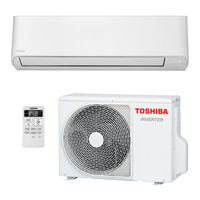
Toshiba RAS-B07J2KVG-E Air Conditioner Manuals
Manuals and User Guides for Toshiba RAS-B07J2KVG-E Air Conditioner. We have
3
Toshiba RAS-B07J2KVG-E Air Conditioner manuals available for free PDF download: Service Manual, Installation Manual, Owner's Manual
Toshiba RAS-B07J2KVG-E Service Manual (138 pages)
Brand:
Toshiba
| Category:
Air Conditioner
| Size: 19.53 MB
Table of Contents
Table of Contents
2
For General Public Use
3
Safety Precautions
3
Warning
4
Specifications
6
Capacity Variation Ratio According to Temperature
9
Operation Characteristic Curve
9
Piping Materials and Joints Used
10
Refrigerant Piping Installation
10
Refrigerant R32
10
Safety During Installation/Servicing
10
Joints
11
Minimum Thicknesses of Socket Joints
11
Processing of Piping Materials
11
Thicknesses of Annealed Copper Pipes
11
Dimensions Related to Flare Processing for R22
12
Dimensions Related to Flare Processing for R32(R410A)
12
Flare Processing
12
Flare Processing Dimensions
12
Flare and Flare Nut Dimensions for R22
13
Flare Connecting Procedures and Precautions
13
Relations between Flare Nut and Flare Seal Surface
13
Tightening Torque of Flare for R32(R410A) [Reference Values]
13
General Tools
14
Required Tools
14
Tools Exclusive for R32
14
Configuration of Refrigerant Charging
15
Recharging of Refrigerant
15
Brazing of Pipes
16
Flux
16
Materials for Brazing
16
Silver Brazing Filler
16
Brazing
17
Brazing Method to Prevent Oxidation
17
Characteristics Required for Flux
17
Types of Flux
17
Construction Views
18
Indoor Unit
18
Outdoor Unit
19
Wiring Diagram
21
Specifications of Electrical Parts
24
Refrigerant Cycle Diagram
25
Cooling
29
Heating
29
Operation Data
29
Control Block Diagram
30
Outdoor Unit (Inverter Assembly)
31
Operation Description
33
Outline of Air Conditioner Control
33
Role of Outdoor Unit Controller
33
Basic Operation
35
Control Contents of Remote Controller
35
Indoor Unit Control
35
Operation Control
35
Outdoor Unit Control
35
AUTO Operation
36
Cooling/Heating Operation
36
DRY Operation
36
Indoor Fan Air Flow Rate
37
Indoor Fan Motor Control
37
Outdoor Fan Motor Control
40
Capacity Control
41
Current Release Control
41
Release Protective Control by Temperature of Indoor Heat Exchanger
42
Defrost Control (Only in Heating Operation)
43
Defrost Operation
43
Finish of Defrost Operation
43
Start of Heating Operation
43
Air Direction Adjustment
44
Louver Control
44
Louver Position
44
Swing
44
Cooling Operation
45
ECO Operation
45
Heating Operation
45
Discharge Temperature Control
46
High Pressure Control
46
Temporary Operation
46
Pulse Modulating Valve (P .M.V.) Control
47
Self-Cleaning Function
48
Self-Cleaning Operation Times
48
Self-Cleaning Diagram
49
Self-Cleaning Function Release
49
Hi-POWER Mode
50
Remote-A or B Selection
50
Setting the Remote Controller
50
Display Lamp Brightness Adjustment
51
Operating System Setting
51
Operation Mode Select Table
51
To Decrease the Display Lamp Brightness or Turn It off
51
Eco and Silent Operation
52
QUIET Mode
52
Silent Operation
52
Silent Operation Description
52
How to Set the a Uto Restart Function
53
When the Unit Is in Operation
53
When the Unit Is Standby
53
How to Cancel the Auto Restart Function
54
Power Failure During Timer Operation
54
When the System Is Operating
54
Automatic Operation
55
Cooling / Heating / Fan Only Operation
55
Parts Name of Remote Contr Oller
55
Remote Controller and Its Fuctions
55
ECO and SILENT Operation Setting
56
Timer Operation
56
Manual Deforst Operation
57
Name and Functions of Indications on Remote Controller
57
Before Installing the Wireless Remote Controller
58
Installation Diagram of Indoor and Outdoor Units
58
Installation Procedure
58
Fixing Bolt Arrangement of Outdoor Unit
59
Installation
59
Optional Installation Parts
59
Accessory and Installation Parts
60
Changes in the Product and Components
61
Installation/Servicing Tools
61
New Tools for R32(R410A)
61
Cutting a Hole
62
Cutting a Hole and Mounting Installation
62
Installation Place
62
Mounting the Installation Plate
62
Die-Cutting Back Body Slit
63
How to Remove the Drain Hose
63
Piping and Drain Hose Forming
63
Piping and Drain Hose Installation
63
How to Fix the Drain Cap
64
In Case of Bottom Right or Bottom Left Piping
64
Left-Hand Connection with Piping
64
To Connect the Pipe after Installation of the Unit (Figure)
64
Drainage
65
Indoor Unit Fixing
65
Precautions for Adding Refrigerant
66
Draining the Water
67
Refrigerant Piping Connection
68
Tightening Connection
68
Air Purge
69
Packed Valve Handling Precautions
69
Using a Vacuum Pum
69
Electrical Works
70
How to Install the Air Inlet Grille on the Indoor Unit
70
Wiring Connection
70
In Case of Indoor Unit Connect with 1:1 Outdoor Unit
71
Power Supply and Connecting Cable Connection
71
Power Supply Input at Outdoor Unit Terminal Block
71
Power Input at Outdoor Terminal Block
72
Power Supply Input at Indoor Unit Terminal Block
72
In Case of Indoor Unit Connect with Inverter Multi System (IMS)
73
Power Supply Input Wiring Diagram for Inverter Multi System (IMS)
73
Auto Restart Setting
74
Gas Leak Test
74
Remote Control A-B Selection
74
Test Operation
74
How to Diagnose the Trouble
75
Precautions When Handling the New Inverter
75
The Control Circuitry Has an Uninsulated Construction
75
Discharging Method
77
Precautions When Inspecting the Control Section of the Outdoor Unit
77
Confirmation of Power Supply
78
Confirmation of Power Voltage
78
First Confirmation
78
Operation Which Is Not a Trouble
78
Judgment by Flashing LED of Indoor Unit
79
Primary Judgment
79
How to Use Remote Controller in Service Mode
80
Self-Diagnosis by Remote Controller
80
Caution at Servicing
81
Judgment of Trouble by Every Symptom
87
Power Is Not Turned on
87
Power Is Not Turned on Though Indoor P.C. Board Is Replaced
88
Only the Indoor Motor Fan Does Not Operate
91
Indoor Fan Starts Rotating When Power Supply Is Turned on
95
Troubleshooting for Remote Controller
96
Outdoor Unit Does Not Operate
97
Outdoor Unit Stops in a Little While after Operation Started
97
Wiring Failure
97
How to Check Simple the Main Parts
98
How to Diagnose Trouble in Outdoor Unit
99
Summarized Inner Diagnosis of Inverter Assembly
99
How to Check Simply the Main Parts
101
How to Check the P.C. Board
101
Check Procedures
102
P .C . Board Layout
104
Sensor Characteristic Table
104
How to Simply Judge Whether Outdoor Fan Motor Is Good or Bad
108
Turn off the Breaker
108
How to Replace the Main Parts
109
Electric Part Box Assembly
110
Front Panel
110
Fan Motor
111
Horizontal Louver
111
Drain Pan Assembly
112
Cross Flow Fan
113
Vertical Louver Assembly
113
Heat Exchanger
114
Common Procedure
115
Inverter Assembly
117
Compressor
118
Fan Guard
119
Pulse Modulating Valve Coil
119
Control Board Assembly
120
Front Cabinet
122
TD Sensor (Discharge Pipe Temperature Sensor)
128
TO Sensor (Outside Air Temperature Sensor)
128
TS Sensor (Suction Pipe Temperature Sensor)
128
Exploded Views and Parts List
129
Advertisement
Toshiba RAS-B07J2KVG-E Installation Manual (19 pages)
Brand:
Toshiba
| Category:
Air Conditioner
| Size: 3.24 MB
Table of Contents
Table of Contents
2
Precautions for Safety
3
Accessory Parts
6
Installation Diagram of Indoor and Outdoor Units
7
Optional Installation Parts
7
Indoor Unit
8
Installation Place
8
Cutting a Hole and Mounting Installation Plate
8
Piping and Drain Hose Installation
8
Indoor Unit Fixing
9
Drainage
9
Outdoor Unit
10
Installation Place
10
Precautions about Installation in Regions with Snowfall and Cold Temperatures
10
Draining the Water
11
Refrigerant Piping Connection
11
Evacuating
12
Electrical Works
13
In Case of Indoor Unit Connect with 1:1 Outdoor Unit
14
In Case of Indoor Unit Connect with Inverter Multi System (IMS)
16
Others
17
Gas Leak Test
17
Remote Control A-B Selection
17
Test Operation
17
Auto Restart Setting
17
Appendix
18
Toshiba RAS-B07J2KVG-E Owner's Manual (6 pages)
R32 or R410A INVERTER, AIR CONDITIONER SPLIT TYPE, For general public use, Indoor/Outdoor units
Brand:
Toshiba
| Category:
Air Conditioner
| Size: 3.96 MB
Advertisement
Advertisement
Related Products
Toshiba RAS-B07J2KVSG-E
Toshiba RAS-B07J2AVSG-E
Toshiba RAS-B07J2KVG-UA
Toshiba RAS-B07N4KVSG-E
Toshiba RAS-B07BKVG-E
Toshiba RAS-B07G3KVSGB-E
Toshiba RAS-B07CKVG-EE
Toshiba RAS-B07B2KVG-E
Toshiba RAS-B072KVG-UA
Toshiba RAS-B07
Toshiba Categories
Laptop
Air Conditioner
TV
LCD TV
All in One Printer
More Toshiba Manuals
Login
Sign In
OR
Sign in with Facebook
Sign in with Google
Upload manual
Upload from disk
Upload from URL