Sign In
Upload
Manuals
Brands
Sony Manuals
Camcorder
Handycam Vision CCD-TRV512
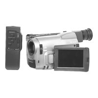
Sony Handycam Vision CCD-TRV512 Camcorder Manuals
Manuals and User Guides for Sony Handycam Vision CCD-TRV512 Camcorder. We have
5
Sony Handycam Vision CCD-TRV512 Camcorder manuals available for free PDF download: Service Manual, Operating Instructions Manual
Sony Handycam Vision CCD-TRV512 Service Manual (212 pages)
VIDEO CAMERA RECORDER
Brand:
Sony
| Category:
DVD Recorder
| Size: 28.51 MB
Table of Contents
Table of Contents
4
Service Note
6
General
7
5 Repair Parts List
26
Disassembly
26
1).Removal of Ma-297 Board, F Panel Assembly and Microphone (Except Trv14E/Trv24E Model)
26
2).Removal of Ma-296 Board, F Panel Assembly and Microphone
26
(Trv14E/Trv24E Model)
26
(Except Trv14E/Trv24E Model)
26
Removal of Cabinet Assembly
27
JK-154/155 and SE-60 BOARD
27
Removal of DD-94 Board
28
REMOVAL of ZOOM LENS, CD-164/165 and IR-28 BOARD
28
Removal of VC-188 Board
29
Removal of Cf-45/46 Board
29
1). Removal of Evf Block Assembly
30
1). REMOVAL of EVF CABINET and VF-102 BOARD
31
2).REMOVAL of EVF CABINET, VF-109, LB-49 and VF-110 BOARD (TRV53 MODEL)
31
3).REMOVAL of EVF CABINET and VF-102 BOARD (EXCEPT TRV53/TRV14E/TRV24E MODEL)
32
1). Removal of P Cabinet and Lcd Assembly (Except Trv14E/Trv24E Model)
33
2). Removal of P Cabinet and Lcd Assembly
33
(Trv14E/Trv24E Model)
33
(Except Trv14E/Trv24E Model)
33
1). Removal of Pd-76/77 Board (Except Trv14E/Trv24E Model)
34
2). Removal of Sd-24/25 and Pd-74/75 Board
34
Trv14E/Trv24E Model
36
Circuit Boards Location
36
Block Diagrams
37
Overall (1) Block Diagram
37
Overall (2) Block Diagram
38
Camera Block Diagram
39
Video/Audio Block Diagram
40
System Control Block Diagram
41
Mode Control Block Diagram
42
Evf Block Diagram
43
Lcd (A) Block Diagram
44
Lcd (B) Block Diagram
45
Lcd (D) Block Diagram
47
Servo Block Diagram
48
Power (1) Block Diagram
49
Printed Wiring Boards and Schematic Diagrams
50
Frame Schematic Diagram
50
Schematic Diagrams
50
Camera 1) Schematic Diagram
53
Camera 2) Schematic Diagram
54
Video) Schematic Diagram
55
Printed Wiring Board and Schematic Diagram
56
In/Out) Schematic Diagram
57
Ld) Schematic Diagram
58
Pj) Schematic Diagram
58
Audio) Schematic Diagram
59
CD-164/165 (CCD Imager)
60
Printed Wiring Board and Schematic Diagram
60
Schematic Diagram
61
Ma-296/297 (Audio) Schematic Diagram
62
System Control
64
Printed Wiring Board
64
Schematic Diagram
64
Rgb Decoder
65
Schematic Diagrams
65
Schematic Diagrams
66
Power) Schematic Diagram
67
Lcd) Schematic Diagram
71
Mf-7800 (Focus) Schematic Diagram
78
Lcd Driver
78
Rgb) Schematic Diagram
79
Rgb) Schematic Diagram
80
Exploded Views
85
Main Section
90
1). Evf Section (Trv53 Model)
91
2). Evf Section (Trv14E/Trv24E Model)
92
3). Evf Section (Except Trv53/Trv14E/Trv24E Model)
93
Zoom Lens Block Section (Lsv-510A)
94
Cassette Compartment Block Section
95
Ls Chassis Block Section
96
Mechanism Chassis Block Section
97
Electrical Parts List
98
Adjustments
130
Camera Section Adjustment
130
Preparations before Adjustment
130
List of Service Tools
130
Precautions
131
Switch Settings
131
Adjustment Sequence
131
Subject
131
Preparations
132
Adjustment Remote Commander (RM-95 Upgraded)
133
Using the Adjustment Remote Commander
133
Precautions When Using the Adjustment Remote Commander
134
Page F Address List
135
Camera System Adjustments
137
Adjustment Points When Major Parts
137
Power Supply Voltage Check (VC-188 Board)
137
Preparation for Adjustment
137
Initialization of Page F Data
138
Page F Data Modification
139
Mhz Crystal Oscillator Adjustment (VC-188 Board)
141
HALL Adjustment
143
Flange Back Adjustment
145
Flange Back Check
146
Picture Frame Setting
147
Color Reproduction Adjustment
148
IRIS IN/OUT Adjustment
149
Auto White Balance Reference Data Input
150
MAX Gain Adjustment
151
Auto White Balance Adjustment
152
White Balance Check
153
Velocity Sensor Sensitivity Adjustment
154
(Except Trv14E)
154
Electronic Viewfinder System Adjustments
155
(VF-102 Board)
155
Power Supply Voltage Check
155
Horizontal and Vertical Position
155
BRIGHT Adjustment
155
Centering Adjustment
156
Focus Adjustment
156
Diffraction Adjustment
156
Color Electronic Viewfinder System
157
Adjustments
157
Power Supply Voltage Check (VF-109 Board)
157
EVR Initial Data Input
158
PCO Adjustment (VF-110 Board)
158
BRIGHT Adjustment (VF-110 Board)
159
CONTRAST Adjustment (VF-110 Board)
159
Back Light Current Consumption Adjustment
160
(VF-109 Board)
160
White Balance Adjustment
160
LCD System Adjustments
161
EVR Initial Data Input
162
VCO Adjustment
163
BRIGHT Adjustment
164
CONTRAST Adjustment
164
D RANGE Adjustment (Type 2, 3 MODEL)
166
V-COM Level Adjustment (Type 2, 3 MODEL)
167
COLOR Adjustment
168
HUE Adjustment (NTSC MODEL)
169
BURST CLEANING Adjustment (PAL MODEL)
169
White Balance Adjustment
171
Mechanism Section Adjustments
172
How to Operate the Mechanism after the Cassette Compartment Is Removed
172
How to Load a Cassette Tape
172
How to Establish RECORD Mode
172
How to Eject a Cassette Tape
172
Processing after Operation
172
Tape Path Adjustment
173
Preparations for Adjustments
173
Video Section Adjustment
174
Preparations before Adjustment
175
Equipment Required
175
Precautions on Adjustment
175
Adjustment Connector (VC-188 Board CN102)
175
Equipment Connection
176
Alignment Tape
176
Output Level and Impedance
177
Adjustment Points When Major Parts Are
178
Replaced
178
When Drum Is Replaced
178
Power Supply System Adjustment
178
Power Supply Voltage Check (VC-188 Board)
178
VTR & CAM Mode on
179
EMG Code (Emergency Code)
180
MSW Code
180
Bit Value Discrimination
181
Initializing the Emergency Code Area
182
LED Check
182
S415, S/S Mode Sw)
182
Key Input Check
183
Key Input Check (A/D Port)
183
Individual Operation of Drum
184
Drum Use History Check
184
System Control System Adjustments
185
Battery down Voltage Adjustment
185
Battery down Voltage Check
185
Servo System Adjustments
186
SYNC Level and BURST Level Adjustments
186
Switching Position Adjustment
187
Capstan FG Offset Adjustment
188
Playback Frequency Response Characteristics Adjustment
189
Demd out Level Adjustment
190
Yd out Level Adjustment
191
Pb Chroma Level Check
192
Pb y out Level Adjustment
193
Fe Osc Check
194
Emphasis Input Level Adjustment
195
Y Fm Deviation Adjustment (Note)
196
Y Fm Carrier Frequency Adjustment
197
CHROMA EMPHASIS Fo ADJUSTMENT
198
Rec y Level Adjustment
199
Rec C Level Adjustment
200
Audio System Adjustment
201
Ee-Output Level Check
201
Mhz DEVIATION ADJUSTMENT
202
(Stereo Model)
202
Mhz DEVIATION ADJUSTMENT
203
(Stereo Model)
203
Mhz DEVIATION ADJUSTMENT
204
(Mono Model)
204
BPF Fo ADJUSTMENT
204
Overall Signal Level, Distortion and Separation Check
205
Overall Noise Level Check
205
Infrared Transmit Circuit Adjustment
206
(Ir Model)
206
Preparations
206
Equipment Connection
206
Switch Setting
206
Video Carrier Frequency Adjustment
207
Video Deviation Adjustment
208
Audio Deviation Adjustment
209
Advertisement
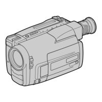
Sony Handycam Vision CCD-TRV512 Operating Instructions Manual (76 pages)
Video Camera Recorder
Brand:
Sony
| Category:
Camcorder
| Size: 1.72 MB
Table of Contents
Operating Instructions
1
Table of Contents
3
Before You Begin Using this Manual
4
Precautions on Camcorder Care
5
Checking Supplied Accessories
6
Getting Started
7
Charging and Installing the Battery Pack
7
Installing the Battery Pack
9
Inserting a Cassette
10
Basic Operations Camera Recording
11
To Focus the Viewfinder Lens
12
Using the Zoom Feature
13
Selecting the Start/Stop Mode
14
Shooting with the LCD Screen
15
Letting the Subject Monitor the Shot
16
Hints for Better Shooting
17
Checking the Recorded Picture
19
Playing Back a Tape
21
Searching for the End of the Picture
23
Advanced Operations Using Alternative Power Sources
24
Using a Car Battery
26
Changing the Mode Settings
27
Selecting the Mode Setting of each Item
28
Recording with the Date or Time
30
Fade-In and Fade-Out
31
Enjoying Picture Effect
32
Using Picture Effect Function
33
Using the Wide Mode Function
34
Focusing Manually
36
Using the PROGRAM AE Function
37
Shooting with Backlighting
38
Releasing the STEADY SHOT Function
39
Superimposing a Title
40
Making Your Own Titles
43
Watching on a TV Screen
45
Editing Onto Another Tape
47
Additional Information Changing the Lithium Battery in the Camcorder
48
Changing the Lithium Battery in the Camcorder
49
Resetting the Date and Time
50
Playback Modes
52
Tips for Using the Battery Pack
53
Maintenance Information and Precautions
56
Video Head Cleaning
57
Using Your Camcorder Abroad
61
Trouble Check
62
Specifications
66
Identifying the Parts
68
Remote Commander
72
Warning Indicators
75
Index
76
Sony Handycam Vision CCD-TRV512 Operating Instructions Manual (76 pages)
Video Camera Recorder
Brand:
Sony
| Category:
Camcorder
| Size: 4.58 MB
Advertisement
Sony Handycam Vision CCD-TRV512 Service Manual (33 pages)
video 8 Handycam
Brand:
Sony
| Category:
Camcorder
| Size: 12.34 MB
Sony Handycam Vision CCD-TRV512 Service Manual (33 pages)
VIDEO CAMERA RECORDER
Brand:
Sony
| Category:
Camcorder
| Size: 12.4 MB
Advertisement
Related Products
Sony CCD-TRV512 - Video Camera Recorder 8mm
Sony CCD-TRV57WR - Video Camera Recorder 8mm
Sony CCD-TRV52 - Video Camera Recorder 8mm
Sony CCD-TRV53 - Video Camera Recorder 8mm
Sony Handycam Vision CCD-TRV56E
Sony HANDYCAM VISION CCD-TRV55E
SONY Handycam Vision CCD-TRV57
Sony CCD-TRV58E
Sony Handycam Vision CCD-TRV52
Sony Handycam Vision CCD-TRV53
Sony Categories
Laptop
TV
CD Player
Camcorder
Digital Camera
More Sony Manuals
Login
Sign In
OR
Sign in with Facebook
Sign in with Google
Upload manual
Upload from disk
Upload from URL