Sign In
Upload
Manuals
Brands
Sony Manuals
Camcorder
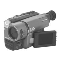
Handycam CCD-TR716
Sony Handycam CCD-TR716 Manuals
Manuals and User Guides for Sony Handycam CCD-TR716. We have
4
Sony Handycam CCD-TR716 manuals available for free PDF download: Service Manual, Operating Instructions Manual
Sony Handycam CCD-TR716 Service Manual (234 pages)
VIDEO CAMERA RECORDER
Brand:
Sony
| Category:
Camcorder
| Size: 24.04 MB
Table of Contents
Camera Recording
2
Service Note
5
Service Note
5
To Take out a Cassette When Not Eject (Force Eject)
5
Self-Diagnosis Function
6
Self-Diagnosis Display
6
Service Mode Display
6
Display Method
6
Switching of Backup no
6
End of Display
6
Self-Diagnosis Code Table
7
Table of Contents
8
General
11
This Section Is Extacked from Instruction Manual of
11
CCD-Trv36/Trv43/Trv46
11
Disassembly
31
Removal of Front Panel Block and Video Light Block
31
Removal of LB-54, VF-119 and VF-120 Boards (Color View Finder Models)
32
CRT Assembly (B/W View Finder Models)
32
Removal of Cabinet (R) Block
33
Removal of Cassette Lid Assembly
33
Removal of Battery Panel Block
33
Removal of Cabinet (L) Block
34
Removal of Control Switch Block (FK-8500)
34
Removal of Zoom Lens Block and VL-20/21 Board
34
Removal of DD-117 and PJ-90/91 Boards
34
Removal of VC-215 Abd SE-80/81 Boards
35
Removal of View Finder Block
35
Removal of TR Cover, CF-60 Board and Display Panel (TR Series)
36
Removal of IR Cover, CF-61 Board and LCD Panel (TRV Series)
36
Display Panel (TR Series)
36
Service Position
37
Circuit Boards Location
38
Flexible Boards and Flat Cables Location
38
Block Diagrams
39
Overall Block Diagram
39
Camera/Video 1 Block Diagram
40
Vtr/Camera Control Block Diagram
41
Servo Block Diagram
42
Mode Control Block Diagram
43
Audio Block Diagram
44
LCD Block Diagram (TRV Model)
45
Color EVF Block Diagram (Color EVF Model)
46
B/W Evf Block Diagram B/W Evf Model
47
Power Block Diagram
48
Frame Schematic Diagram (1)
49
Printed Wiring Boards and Schematic Diagrams
49
CD-210/211 (CCD Imager) Board
51
Adjustments
82
Camera Section Adjustments
82
Preparations before Adjustment (Camera Section)
82
List of Service Tools
82
Preparations
83
Setting the Switch
86
Adjusting Procedure
86
Subject
86
Adjusting Remote Commander
87
Using the Adjusting Remote Commander
87
Precautions Upon Using the Adjusting Remote Commander
87
Data Processing
88
Initialization of D, E, F
89
Modification of D, E, F
89
Camera System Adjustments
95
G-CAM Flip Adjustment
95
Hall Adjustment
96
Flange Back Adjustment
97
Flange Back Adjustment (1)
97
Flange Back Adjustment (2)
97
Flange Back Check
98
Picture Frame Setting
98
Color Reproduction Adjustment
99
IRIS IN/OUT Adjustment
100
MAX GAIN Adjustment
100
Auto White Balance Standard Data Input
101
Auto White Balance Adjustment
101
White Balance Check
102
Angular Velocity Sensor Sensitivity Check
103
(CCD-Tr416/Tr416Pk/Tr516/Tr516Pk/Tr716)
104
EVF Initial Data Input
104
VCO Adjustment (VF-119 Board)
105
Bright Adjustment (VF-119 Board)
105
Contrast Adjustment (VF-119 Board)
106
Backlight Consumption Current Adjustment (VF-120 Board)
106
Monochrome Electronic Viewfinder System Adjustments
107
Horizontal Slant Check
107
Centering Adjustment
107
Focus Adjustment
107
Aberration Adjustment
108
Horizontal Amplitude Adjustment (VF-99 Board)
108
Vertical Amplitude Adjustment (VF-99 Board)
109
Brightness Adjustments (VF-99 Board)
109
Horizontal Amplitude, Vertical Amplitude
109
LCD System Adjustment (TRV Series)
110
LCD Initial Data Input
110
VCO Adjustment (PD-107 Board)
111
D Range Adjustment (PD-107 Board)
111
Bright Adjustment (PD-107 Board)
112
Contrast Adjustment (PD-107 Board)
112
V-COM Adjustment (PD-107 Board)
113
Color Adjustment (PD-107 Board)
113
V-COM Adjustment (PD-107 Board)
114
White Balance Adjustment (PD-107 Board)
114
Mechanical Section Adjustment
115
Operating Without a Cassette
115
Tape Path Adjustment
115
Preparations for Adjustments
115
Video Section Adjustments
116
Preparations before Adjustment
116
Equipments to be Used
116
Precautions on Adjusting
117
Adjusting Connectors
117
Connecting the Equipments
118
Alignment Tape
118
Output Level and Impedance
120
Recording Mode (Standard 8/Hi8) Switching
120
(Hi8 Model)
120
Service Mode
120
Test Mode Setting
120
Emergency Memory Address
121
EMG CODE (Emergency Code)
121
MSW Codes
122
Bit Value Discrimination
123
Switch Check (1)
123
Switch Check (2)
124
Headphone Jack Check
124
Input/Output Selection Check
124
LED, LCD (Display Window) Check
125
Record of Use Check
125
System Control System Adjustment
126
Initialization of D, E, F
126
Battery End Adjustment (VC-215 Board)
126
Servo System Adjustments
127
CAP FG Offset Adjustment (VC-215 Board)
127
Switching Position Adjustment (VC-215 Board)
127
Video System Adjustments
128
Mhz Origin Oscillation Adjustment (VC-215 Board)
128
AFC F0 Adjustment (VC-215 Board)
129
Filter F0 Adjustment (VC-215 Board)
129
Y out Level Adjustment (VC-215 Board)
130
C out Level Adjustment (VC-215 Board)
130
RP Filter F0 Adjustment (VC-215 Board)
131
Hi8 REC y Current Adjustment (VC-215 Board)
132
CCD-Trv16/Trv16Pk
133
Hi8 REC L Level Adjustment (VC-215 Board)
134
Standerd8 REC L Level Adjustment
135
CCD-Trv16/Trv16Pk
136
REC C Current Adjustment (VC-215 Board)
136
IR Transmitter Adjustments (CCD-TRV43/TRV46/TRV46PK)
137
IR Video Carrier Frequency Adjustment (VC-215 Board)
137
IR Video Deviation Adjustment (VC-215 Board)
137
IR Audio Deviation Adjustment (VC-215 Board)
138
Mhz Deviation Adjustment (VC-215 Board)
139
BPF Adjustment (VC-215 Board)
139
Arrangement Diagram for Adjustment Parts
140
Repair Parts List
141
Exploded Views
141
Remote Commander and Cassette Lid Assembly
141
Cabinet (L) and Battery Panel Assembly
142
Front Panel Block Assembly
143
Cabinet (R) Block Assembly (TR Series)
144
Cabinet (R) Block Assembly (TRV Series)
145
Main Boards Block Assembly
146
B/W EVF Block Assembly (CCD-TR315 and TRV Series)
148
LCD Block Assembly (TRV Series)
149
Zoom Lens Block Assembly
150
Cassette Compartment Assembly
151
LS Chassis Assembly
152
Mechanism Chassis Assembly
153
Electrical Parts List
154
Advertisement
Sony Handycam CCD-TR716 Service Manual (177 pages)
8 Video Camera Recorder Hi 8 Video Camera Recorder
Brand:
Sony
| Category:
Camcorder
| Size: 11.39 MB
Table of Contents
Service Note
5
To Take out a Cassette When Not Eject (Force Eject)
5
Self-Diagnosis Function
6
Self-Diagnosis Display
6
Service Mode Display
6
Display Method
6
Switching of Backup no
6
End of Display
6
Self-Diagnosis Code Table
7
Table of Contents
8
General
11
This Section Is Extacked from Instruction Manual of
11
CCD-Trv36/Trv43/Trv46
11
Disassembly
31
Removal of Front Panel Block and Video Light Block
31
Removal of LB-54, VF-119 and VF-120 Boards (Color View Finder Models)
32
CRT Assembly (B/W View Finder Models)
32
Removal of Cabinet (R) Block
33
Removal of Cassette Lid Assembly
33
Removal of Battery Panel Block
33
Removal of Cabinet (L) Block
34
Removal of Control Switch Block (FK-8500)
34
Removal of Zoom Lens Block and VL-20/21 Board
34
Removal of DD-117 and PJ-90/91 Boards
34
Removal of VC-215 Abd SE-80/81 Boards
35
Removal of View Finder Block
35
Removal of TR Cover, CF-60 Board and Display Panel (TR Series)
36
Removal of IR Cover, CF-61 Board and LCD Panel (TRV Series)
36
Service Position
37
Circuit Boards Location
38
Flexible Boards and Flat Cables Location
38
Adjustments
82
Camera Section Adjustments
82
Preparations before Adjustment (Camera Section)
82
List of Service Tools
82
Preparations
83
Precautions
86
Setting the Switch
86
Adjusting Procedure
86
Subject
86
Adjusting Remote Commander
87
Using the Adjusting Remote Commander
87
Precautions Upon Using the Adjusting Remote Commander
87
Data Processing
88
Initialization of D, E, F
89
Modification of D, E, F
89
D Page Table
90
F Page Table
91
E Page Table
93
Camera System Adjustments
95
G-CAM Flip Adjustment
95
Hall Adjustment
96
Flange Back Adjustment
97
Flange Back Adjustment (1)
97
Flange Back Adjustment (2)
97
Flange Back Check
98
Picture Frame Setting
98
Color Reproduction Adjustment
99
IRIS IN/OUT Adjustment
100
MAX GAIN Adjustment
100
Auto White Balance Standard Data Input
101
Auto White Balance Adjustment
101
White Balance Check
102
Angular Velocity Sensor Sensitivity Check
103
(CCD-Tr416/Tr416Pk/Tr516/Tr516Pk/Tr716)
104
EVF Initial Data Input
104
VCO Adjustment (VF-119 Board)
105
Bright Adjustment (VF-119 Board)
105
Contrast Adjustment (VF-119 Board)
106
Backlight Consumption Current Adjustment (VF-120 Board)
106
Monochrome Electronic Viewfinder System Adjustments
107
Horizontal Slant Check
107
Centering Adjustment
107
Focus Adjustment
107
Aberration Adjustment
108
Horizontal Amplitude Adjustment (VF-99 Board)
108
Vertical Amplitude Adjustment (VF-99 Board)
109
Brightness Adjustments (VF-99 Board)
109
Horizontal Amplitude, Vertical Amplitude
109
LCD System Adjustment (TRV Series)
110
LCD Initial Data Input
110
VCO Adjustment (PD-107 Board)
111
D Range Adjustment (PD-107 Board)
111
Bright Adjustment (PD-107 Board)
112
Contrast Adjustment (PD-107 Board)
112
V-COM Adjustment (PD-107 Board)
113
Color Adjustment (PD-107 Board)
113
V-COM Adjustment (PD-107 Board)
114
White Balance Adjustment (PD-107 Board)
114
Mechanical Section Adjustment
115
Operating Without a Cassette
115
Tape Path Adjustment
115
Preparations for Adjustments
115
Video Section Adjustments
116
Preparations before Adjustment
116
Equipments to be Used
116
Precautions on Adjusting
117
Adjusting Connectors
117
Connecting the Equipments
118
Alignment Tape
118
Output Level and Impedance
120
Recording Mode (Standard 8/Hi8) Switching
120
(Hi8 Model)
120
Service Mode
120
Test Mode Setting
120
Emergency Memory Address
121
EMG CODE (Emergency Code)
121
MSW Codes
122
Bit Value Discrimination
123
Switch Check (1)
123
Switch Check (2)
124
Headphone Jack Check
124
Input/Output Selection Check
124
LED, LCD (Display Window) Check
125
Record of Use Check
125
System Control System Adjustment
126
Initialization of D, E, F
126
Battery End Adjustment (VC-215 Board)
126
Servo System Adjustments
127
CAP FG Offset Adjustment (VC-215 Board)
127
Switching Position Adjustment (VC-215 Board)
127
Video System Adjustments
128
Mhz Origin Oscillation Adjustment (VC-215 Board)
128
AFC F0 Adjustment (VC-215 Board)
129
Filter F0 Adjustment (VC-215 Board)
129
Y out Level Adjustment (VC-215 Board)
130
C out Level Adjustment (VC-215 Board)
130
RP Filter F0 Adjustment (VC-215 Board)
131
Hi8 REC y Current Adjustment (VC-215 Board)
132
CCD-Trv16/Trv16Pk
133
Hi8 REC L Level Adjustment (VC-215 Board)
134
Standerd8 REC L Level Adjustment (VC-215 Board) (CCD-TR315/TR416/TR416PK CCD-TRV16/TRV16PK)
135
REC C Current Adjustment (VC-215 Board)
136
IR Transmitter Adjustments (CCD-TRV43/TRV46/TRV46PK)
137
IR Video Carrier Frequency Adjustment (VC-215 Board)
137
IR Video Deviation Adjustment (VC-215 Board)
137
IR Audio Deviation Adjustment (VC-215 Board)
138
Mhz Deviation Adjustment (VC-215 Board)
139
BPF Adjustment (VC-215 Board)
139
Repair Parts List
141
Exploded Views
141
Remote Commander and Cassette Lid Assembly
141
Cabinet (L) and Battery Panel Assembly
142
Front Panel Block Assembly
143
Cabinet (R) Block Assembly (TR Series)
144
Cabinet (R) Block Assembly (TRV Series)
145
Main Boards Block Assembly
146
B/W EVF Block Assembly (CCD-TR315 and TRV Series)
148
LCD Block Assembly (TRV Series)
149
Zoom Lens Block Assembly
150
Cassette Compartment Assembly
151
LS Chassis Assembly
152
Mechanism Chassis Assembly
153
Electrical Parts List
154
Sony Handycam CCD-TR716 Operating Instructions Manual (76 pages)
Video Camera Recorder Hi8
Brand:
Sony
| Category:
Camcorder
| Size: 3.77 MB
Advertisement
Sony Handycam CCD-TR716 Service Manual (25 pages)
VIDEO CAMERA RECORDER
Brand:
Sony
| Category:
Camcorder
| Size: 9.38 MB
Table of Contents
CCD Imager
2
Servo/System Control
8
Mode Control
12
Rgb Decoder
19
Lcd Drive
20
Back Light, Lcd
21
Board (Side B)
22
Advertisement
Related Products
Sony CCD-TR714 - Video Camera Recorder 8mm
Sony Handycam CCD-TR71
Sony Handycam CCD-TR717E
Sony Handycam CCD-TR713E
Sony Handycam CCD-TR710
Sony CCD-TR718E
Sony Handycam CCD-TR714
Sony Video 8 Handycam CCD-TR7
Sony Handycam CCD-TR740E
Sony Handycam CCD-TR72
Sony Categories
Laptop
TV
CD Player
Camcorder
Digital Camera
More Sony Manuals
Login
Sign In
OR
Sign in with Facebook
Sign in with Google
Upload manual
Upload from disk
Upload from URL