Sign In
Upload
Manuals
Brands
Sony Manuals
Camcorder
Handycam CCD-TR506PK
Sony Handycam CCD-TR506PK Manuals
Manuals and User Guides for Sony Handycam CCD-TR506PK. We have
1
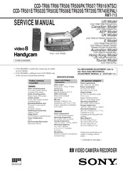
Sony Handycam CCD-TR506PK manual available for free PDF download: Service Manual
Sony Handycam CCD-TR506PK Service Manual (203 pages)
VIDEO CAMERA RECORDER
Brand:
Sony
| Category:
Camcorder
| Size: 12.1 MB
Table of Contents
Table of Contents
4
Service Note
6
Disassembly
25
REMOVAL of MA-295 BOARD, F PANEL ASSEMBLY and MICROPHONE
25
Removal of Cabinet Assembly
25
Removal of Cassette Lid Assembly, Ls Lid
26
Removal of DD-94 Board
26
Removal of Zoom Lens
27
Removal of VC-188 Board
27
Removal of Cf-44 Board
28
Removal of Evf Block Assembly
28
REMOVAL of EVF CABINET and VF-102 BOARD (EVF B/W SECTION)
29
Board (Evf Color Section)
29
Internal Views
30
Circuit Boards Location
31
Mode Sensor)
31
CCD Imager)
31
Infrared Communication)
31
System Control)
31
Back Light)
31
Rgb Decoder)
31
Steady Shot)
31
Repair Parts List
62
Exploded Views
62
Overall Section
62
Cabinet (L), F Panel Section
63
Cabinet (R) Section
64
Main Section
65
Evf Section (Color Evf Model)
66
Evf Section (B/W Evf Model)
67
Zoom Lens Block Section (Lsv-510A)
68
Cassette Compartment Block Section
69
Ls Chassis Block Section
70
Mechanism Chassis Block Section
71
Electrical Parts List
72
Ref. no
72
Part no
72
Description Remarks
72
Ref. no
73
Part no
73
Description Remarks
74
S002
76
Adjustments
96
Camera Section Adjustment
96
Preparations before Adjustment
96
List of Service Tools
96
Precautions
97
Switch Settings
97
Adjustment Sequence
97
Subject
97
Using the Adjustment Remote Commander
99
Precautions When Using the Adjustment Remote Commander
100
1-1-5.Page F Address List
101
Camera System Adjustments
103
Adjustment Points When Major Parts
103
Power Supply Voltage Check (VC-188 Board)
103
Preparation for Adjustment
103
Initialization of Page F Data
104
Page F Data Modification
105
Mhz Crystal Oscillator Adjustment (VC-188 Board)
107
HALL Adjustment
109
Flange Back Adjustment
111
Flange Back Check
112
Picture Frame Setting
113
Color Reproduction Adjustment
114
IRIS IN/OUT Adjustment
115
Auto White Balance Reference Data Input
116
MAX Gain Adjustment
117
Auto White Balance Adjustment
118
White Balance Check
119
Velocity Sensor Sensitivity Adjustment
120
Electronic Viewfinder System Adjustments
121
(VF-102 Board)
121
Power Supply Voltage Check
121
Horizontal and Vertical Position
121
BRIGHT Adjustment
121
Centering Adjustment
122
Focus Adjustment
122
Diffraction Adjustment
122
Color Electronic Viewfinder System
123
Adjustments
123
Power Supply Voltage Check (VF-109 Board)
123
EVR Initial Data Input
124
PCO Adjustment (VF-110 Board)
124
BRIGHT Adjustment (VF-110 Board)
125
CONTRAST Adjustment (VF-110 Board)
125
Back Light Current Consumption Adjustment
126
(VF-109 Board)
126
White Balance Adjustment
126
Mechanism Section Adjustments
128
How to Operate the Mechanism after the Cassette Compartment Is Removed
128
How to Load a Cassette Tape
128
How to Establish RECORD Mode
128
How to Eject a Cassette Tape
128
Processing after Operation
128
Tape Path Adjustment
129
Preparations for Adjustments
129
Video Section Adjustment
130
Preparations before Adjustment
131
3-1-1.Equipment Required
131
3-1-2.Precautions on Adjustment
131
3-1-3.Adjustment Connector (VC-188 Board CN102)
131
3-1-4.Equipment Connection
132
3-1-5.Alignment Tape
132
3-1-6.Output Level and Impedance
133
Adjustment Points When Major Parts
134
Are Replaced
134
When Drum Is Replaced
134
Power Supply System Adjustment
134
Power Supply Voltage Check (VC-188 Board)
134
VTR & CAM Mode on
135
EMG Code (Emergency Code)
136
MSW Code
136
Bit Value Discrimination
137
Initializing the Emergency Code Area
138
LED Check
138
Key Input Check (CF-44 Board IC402 @¶, @• S415, S/S MODE SW)
138
Key Input Check
138
Key Input Check (A/D Port)
139
Individual Operation of Drum, Capstan and Loading Motor
140
Drum Use History Check
140
System Control System Adjustments
141
Battery down Voltage Adjustment
141
Battery down Voltage Check
141
Servo System Adjustments
142
SYNC Level and BURST Level Adjustments
142
Switching Position Adjustment
143
Capstan FG Offset Adjustment
144
Playback Frequency Response Characteristics Adjustment
145
Demd out Level Adjustment
146
Yd out Level Adjustment
147
Pb Chroma Level Check
148
Pb y out Level Adjustment
149
Fe Osc Check
150
Emphasis Input Level Adjustment
151
Y Fm Deviation Adjustment (Note)
152
Y Fm Carrier Frequency Adjustment
153
CHROMA EMPHASIS Fo ADJUSTMENT
154
Rec y Level Adjustment
155
Rec C Level Adjustment
156
Audio System Adjustment
157
Ee-Output Level Check
157
Mhz DEVIATION ADJUSTMENT
158
(Stereo Model)
158
Mhz DEVIATION ADJUSTMENT
159
(Stereo Model)
159
Mhz DEVIATION ADJUSTMENT
160
(Mono Model)
160
BPF Fo ADJUSTMENT
160
Overall Signal Level, Distortion and Separation Check
161
Overall Noise Level Check
161
Infrared Transmit Circuit Adjustment
162
Preparations
162
Equipment Connection
162
Switch Setting
162
Deviation Adjustment
163
Video Deviation Adjustment
164
Audio Deviation Adjustment
165
Advertisement
Advertisement
Related Products
Sony video Hi8 Handycam CCD-TR500
Sony Handycam CCD-TR501E
Sony Handycam CCD-TR502E
Sony Handycam CCD-TR503E
Sony Handycam CCD-TR506E
Sony Handycam CCD-TR506
Sony Handycam CCD-TR507
Sony CCD-TR514 - Video Camera Recorder 8mm
Sony HANDYCAM CCD-TR560
Sony CCD-TR516 - Video Camera Recorder Hi8&trade
Sony Categories
Laptop
TV
Camcorder
CD Player
Digital Camera
More Sony Manuals
Login
Sign In
OR
Sign in with Facebook
Sign in with Google
Upload manual
Upload from disk
Upload from URL