Sign In
Upload
Manuals
Brands
MOTOROLA Manuals
Portable Radio
HT 1000 Series
MOTOROLA HT 1000 Series Manuals
Manuals and User Guides for MOTOROLA HT 1000 Series. We have
4
MOTOROLA HT 1000 Series manuals available for free PDF download: Service Manual, Theory/Troubleshooting Manual, Quick Reference Card
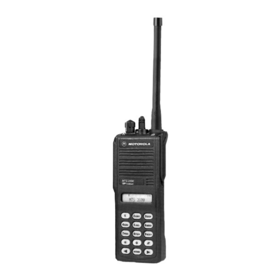
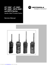
MOTOROLA HT 1000 Series Service Manual (170 pages)
MTX Series
Brand:
MOTOROLA
| Category:
Portable Radio
| Size: 9.74 MB
Table of Contents
Table of Contents
5
List of Tables
10
Model Numbering System
12
Model Charts Model Programming, Flashing, and Cloning
13
Model Charts General Description
13
Programming, Flashing, and Cloning
13
MODEL CHART, Conventional Systems Radios (HT 1000 Models)
14
MODEL CHART, Conventional Systems Radios (JT 1000 and MT 2000 Models)
15
MODEL CHART, Private Systems Radios (MTS 2000 Models)
16
MODEL CHART, Shared Systems Radios
17
MTX 9000 Models)
17
List of Antennas
18
List of Batteries
18
Maintenance Specifications for VHF Radios
19
Maintenance Specifications for UHF Radios
19
Maintenance Specifications for 800Mhz Radios
20
Maintenance Specifications for 900Mhz Radios
20
Glossary
21
1 Introduction
23
2 Test Equipment, Service Aids, and Tools
25
Recommended Test Equipment
25
Table 1 Recommended Test Equipment
25
Service Aids and Recommended Tools
26
Field Programming
26
Table 2 Service Aids
27
Table 3 Recommended Service Tools
28
3 Transceiver Performance Testing
29
General
29
Setup
29
Test Mode
29
Table 4 Equipment Initial Control Settings
29
Table 5 Test Environments, HT 1000/JT 1000 Radios
30
Table 6 Test Frequencies, HT 1000 / JT 1000
31
Table 7 Test Environments, MT 2000, MTS 2000, and MTX Series Radios
34
Table 8 Test Frequencies, MT 2000, MTS 2000, and MTX Series Radios
34
Table 9 Receiver Performance Checks
35
Table 10 Transmitter Performance Checks
36
4 Error-Code Displays
37
Power-Up Display Codes
37
Table 11 Power-Up Display Codes
37
Operational Display Codes
38
Table 12 Operational Display Codes
38
5 Radio Alignment Procedure
39
General
39
Reference Oscillator Alignment
41
Table 13 Reference Oscillator Alignment
41
Front-Endpre-Selector VHF/UHF Only)
42
Rated Audio
42
Table 14 Standard Test Modulation (1 Khz Tone)
42
Squelch
43
Transmitter Power
43
Transmit Deviation Balance (Compensation)
44
Table 15 Transmit Power Setting
44
Transmit Deviation Limit
45
Transmit Deviation Limit Reference
45
Table 16 Transmit Deviation Limit
45
VCO Crossover Frequency
46
Table 17 Transmit Deviation Limit Reference
46
Signalling Deviation
49
Alignment Procedure Conclusion
50
Table 18 Signalling Deviation
50
6 Disassembly and Reassembly
51
General
52
Disassembly to Board Level
52
Disassembly of Control Top
56
Disassembly of Front Cover Assembly
57
Reassembly
58
7 Maintenance
63
Introduction
63
Preventive Maintenance
63
Safe Handling of CMOS Devices
64
Repair Procedures and Techniques
64
8 Exploded Views
73
Basic Radios and Basic Radios with Option Mate Optional
74
Top-Display Radios
75
Keypad Radios
76
Uni-Board Radios
77
9 Component Location Diagrams, Parts Lists, and Schematic Diagrams
79
Introduction
79
NUD7091B, NUD7092B, NUD/PMUD7095B, and NUD7096B VHF (136-178Mhz) TRANSCEIVER BOARDS' PARTS LIST and COMPONENT LOCATION DIAGRAMS
84
Electrical Parts List, VHF Transceivers NUD7091B, NUD7092B, NUD/PMUD7095B, NUD7096B
85
BOARDS' SCHEMATIC DIAGRAM (Sheet 1 of 2)
86
BOARDS' SCHEMATIC DIAGRAM (Sheet 2 of 2)
87
NUE7265B, NUE7266B, NUE/PMUE7272B, and NUE7274B UHF (403-470Mhz) TRANSCEIVER BOARDS' PARTS LIST and COMPONENT LOCATION DIAGRAMS
88
Nue7274B
89
BOARDS' SCHEMATIC DIAGRAM (Sheet 1 of 2)
90
NUE7265B, NUE7266B, NUE/PMUE7272B, and NUE7274B UHF (403-470Mhz) TRANSCEIVER BOARDS' SCHEMATIC DIAGRAM (Sheet 2 of 2)
91
NUE7267B, NUE7268B, NUE/PMUE7273B, and NUE7275B UHF (450-520Mhz) TRANSCEIVER BOARDS' PARTS LIST and COMPONENT LOCATION DIAGRAMS
92
Nue7275B
93
NUE7267B, NUE7268B, NUE/PMUE7273B, and NUE7275B UHF (450-520Mhz) TRANSCEIVER BOARDS' SCHEMATIC DIAGRAM (Sheet 1 of 2)
94
NUE7267B, NUE7268B, NUE/PMUE7273B, and NUE7275B UHF (450-520Mhz) TRANSCEIVER BOARDS' SCHEMATIC DIAGRAM (Sheet 2 of 2)
95
NUF6410B/C, NUF6498B/C, NUF6500B/C and NUF6501C (800Mhz) TRANSCEIVER BOARDS' PARTS LIST and COMPONENT LOCATION DIAGRAMS
96
Electrical Parts List, Transceivers (800Mhz) NUF6410B/C, NUF6498B/C, NUF6500B/C and NUF6501C
97
NUF6410B/C, NUF6498B/C, NUF6500B/C and NUF6501C (800Mhz) TRANSCEIVER BOARDS' SCHEMATIC DIAGRAM (Sheet 1 of 2)
98
NUF6410B/C, NUF6498B/C, NUF6500B/C and NUF6501C (800Mhz) TRANSCEIVER BOARDS' SCHEMATIC DIAGRAM (Sheet 2 of 2)
99
NUF/PMUF6500D, NUF/PMUF6533A and NUF/PMUF6410D (800Mhz) TRANSCEIVER BOARD PARTS LIST and COMPONENT LOCATION DIAGRAMS
100
Pmuf6410D
101
NUF/PMUF6500D, NUF/PMUF6533A and NUF/PMUF6410D (800Mhz) TRANSCEIVER BOARDS' SCHEMATIC DIAGRAM (Sheet 1 of 2)
102
NUF/PMUF6500D, NUF/PMUF6533A and NUF/PMUF6410D (800Mhz) TRANSCEIVER BOARDS' SCHEMATIC DIAGRAM (Sheet 2 of 2)
103
NUF6499B/C and NUF6502B/C (900Mhz) TRANSCEIVER BOARDS' PARTS LIST and COMPONENT LOCATION DIAGRAMS
104
Electrical Parts List, Transceivers (900Mhz) NUF6499B/C and NUF6502B/C
105
(Sheet 1 of 2)
106
(Sheet 2 of 2)
107
Diagrams
108
Electrical Parts List, Transceiver (900Mhz) NUF/PMUF6499D
109
NUF/PMUF6499D (900Mhz) TRANSCEIVER BOARDS' SCHEMATIC DIAGRAM (Sheet 1 of 2)
110
NUF/PMUF6499D (900Mhz) TRANSCEIVER BOARDS' SCHEMATIC DIAGRAM (Sheet 2 of 2)
111
Ncn6145A/C, Ncn6146A, Ntn7089C, Ncn6129C, Ncn6138A, Ncn6140A/B, Ncn6141A
112
Diagrams
112
Ncn6129C, Ncn6138A, Ncn6140A/B, Ncn/Pmcn6140C, Ncn6141A, Ncn6145A/C
114
Schematic Diagram
114
Ncn6129C, Ncn6138A, Ncn6140A/B, Ncn/Pmcn6140C, Ncn6141A, Ncn6145A/C, Ncn6146A, Ntn7089C Controller Board Digital Section Schematic Diagram
115
Ncn6129C, Ncn6138A, Ncn6140A/B, Ncn/Pmcn6140C, Ncn6141A, Ncn6145A/C, Ncn6146A, Ntn7089C and Pmcn6140C Controller Board Top-Level Schematic
116
Ncn6129C, Ncn6138A, Ncn6140A/B, Ncn/Pmcn6140C, Ncn6141A, Ncn6145A/C, Ncn6146A, Ntn7089C Controller Board Power Section Schematic Diagram
117
Ncn6147A/B, Ncn6150A/B, Ntn7091D, Ntn7620E, Pmcn6147B and Pmcn6150B Controller Board' Parts List and Component Location Diagram
118
Electrical Parts List, Controllers NCN6147A/B, NCN6150A/B, NTN7091D, NTN7620E
119
Pmcn6147B, Pmcn6150B
119
Ncn6147A/B, Ncn6150A/B, Ntn7091D, Ntn7620E, Pmcn6147B and Pmcn6150B Controller Board Analog Section Schematic Diagram
120
Ncn6147A/B, Ncn6150A/B, Ntn7091D, Ntn7620E, Pmcn6147B and Pmcn6150B Controller Board Digital Section Schematic Diagram
121
Ncn6147A/B, Ncn6150A/B, Ntn7091D, Ntn7620E, Pmcn6147B and Pmcn6150B Controller Board Top-Level Schematic
122
Ncn6147A/B, Ncn6150A/B, Ntn7091D, Ntn7620E, Pmcn6147B and Pmcn6150B Controller Board Power Section Schematic Diagram
123
Ntn7512D/E, Ntn7513E, Ntn7857D/E and Ntn7858D/Econtroller Boards' Parts List and Component Location Diagrams
124
UHF and 800Mhz Radios NTN7858D/E Top/No Display 900Mhz Hear Clear Radios
125
Ntn7512D/E, Ntn7513E, Ntn7857D/E and Ntn7858D/Econtroller Board Analog Section Schematic Diagram
126
Ntn7512D/E, Ntn7513E, Ntn7857D/E and Ntn7858D/Econtroller Board Digital Section Schematic Diagram
127
Schematic
128
Ntn7512D/E, Ntn7513E, Ntn7857D/E and Ntn7858D/Econtroller Board Power Section Schematic Diagram
129
Ncn6106C, Ncn/Pmcn6153A/B, and Ncn/Pmcn6176A Controller Boards' Parts List and Component Layout Diagrams
130
Electrical Parts List, Controllers NCN6106C, NCN/PMCN6153A/B, NCN/PMCN6176A
131
Ncn6106C , Ncn/Pmcn6153A/B, Ncn/Pmcn6176A Controller Board Analog Section Schematic Diagram
132
Ncn6106C, Ncn/Pmcn6153A/B and Ncn/Pmcn6176A Controller Board Digital Section Schematic Diagram
133
Schematic
134
Ncn6106C, Ncn/Pmcn6153A/B and Ncn/Pmcn6176A Controller Board Power Section Schematic Diagram
135
Front Cover Display Flex and Controls Flex Schematic Diagrams
136
10 Replacement Parts Ordering
137
Introduction
137
Mail Orders
137
Motorola Online
137
FAX Orders
138
Parts Identification
138
Product Customer Service
138
Telephone Orders
138
Appendix A Table 1. MTS 2000 Single Key Secure Module I/O Definition
140
Appendix A Table 2. Key Variable Loader
142
Appendix A Table 3 - Secure Deviation
145
Appendix A Table 4. RSS Secure Parameters
148
Appendix B Table 1. HT 1000 Models
150
Appendix B Table 2. JT 1000 Models
152
Appendix B Table 3. MT 2000 Models
152
Appendix B Table 4. MTS 2000 Models
155
Appendix B Table 5. MTX Series Models
161
Advertisement
Motorola HT 1000 Series Theory/Troubleshooting Manual (60 pages)
Handie-Talkie Portable Radios
Brand:
Motorola
| Category:
Portable Radio
| Size: 14.71 MB
Table of Contents
Table of Contents
5
Glossary of Terms
8
Introduction
9
Description
9
General
9
Printed Circuit Boards and Flexible Circuits
9
Theory of Operation (Basic Functional Description)
10
Purpose
9
Introduction
10
Radio Power
10
B+ Routing and DC Voltage Distribution
10
VHF or UHF Transceiver)
10
800 Or 900Mhz Transceiver)
10
General
10
Antenna Switch
12
Frequency Generation Unit (See Figure 2)
12
Receiver Front End (See Figure 3)
12
Receiver Back End (See Figure 3)
13
Transmitter (See Figure 4)
13
Vhf/Uhf Transceiver Board
12
800/900Mhz TRANSCEIVER BOARD
14
Antenna Switch
14
Frequency Generation Unit (See Figure 5)
14
Receiver Front End (See Figure 6)
14
Receiver Back End (See Figure 6)
15
Transmitter (See Figure 7)
15
Closed Architecture Controller
16
Audio Signalling Architecture
16
Digital Architecture
16
General (See Figure 8)
16
General (See Figure 9)
16
Audio Signalling Architecture
17
Digital Architecture
17
Theory of Operation (Detailed Functional Description)
18
Open Architecture Controller
16
Introduction
18
Radio Power
18
General
18
And a VHF or UHF Transceiver)
18
B+ Routing and DC Voltage Distribution
19
And an 800 or 900Mhz Transceiver)
19
Vhf/Uhf Transceiver
20
Frequency Generation Unit (FGU)
20
Antenna Switch
21
Receiver Front End
21
Receiver Back End
22
Transmitter
22
800/900Mhz TRANSCEIVER BOARD
23
Frequency Synthesis
23
Antenna Switch
24
Receiver Front End
24
Receiver Back End
25
Transmitter
25
Closed Architecture Controller
25
Microcomputer (U705)
25
Controller Board Circuit Operation
27
Open Architecture Controller
29
Microprocessor (U705) and Associated Circuits
30
Controller Board Circuit Operation
32
UNIVERSAL CONNECTOR (See Tables 2 and 3)
36
Troubleshooting
38
Introduction
38
Troubleshooting Procedure
38
Check Batteries
38
Alignment
38
Check Overall Transmitter Operation
38
Check Overall Receiver Operation
39
Troubleshooting Charts
39
(VHF/UHF Transceiver/Closed Architecture Controller)
40
(800/900Mhz Transceiver/Open Architecture Controller)
41
(VHF/UHF Transmitter RF)
42
(800/900Mhz Transmitter RF)
43
(VHF/UHF Receiver RF)
44
(800/900Mhz Receiver RF)
45
(VHF/UHF DC Switch)
46
(800/900Mhz DC Switch)
47
(VHF/UHF Frequency Generation Unit - FGU)
48
(800/900Mhz Frequency Generation Unit - FGU)
49
(VHF/UHF Voltage Controlled Oscillator - VCO)
50
(800/900Mhz Voltage Controlled Oscillator - VCO)
51
(VHF/UHF, Closed Architecture, no Receive Audio)
52
(800/900Mhz, Open Architecture, no Receive Audio)
53
(VHF/UHF, Closed Architecture, no Transmit Deviation)
54
(800/900Mhz, Open Architecture, no Transmit Deviation)
55
(Closed Architecture Controller)
56
(Open Architecture Controller)
57
(VHF/UHF Only, VCO Crossover Frequency Tune)
58
Motorola, Inc
60
Voltage Measurement and Signal Tracing
39
Motorola HT 1000 Series Service Manual (66 pages)
Handie-Talkie Portable Radios
Brand:
Motorola
| Category:
Portable Radio
| Size: 0.49 MB
Table of Contents
Table of Contents
2
Model Numbering System
5
List of Models
6
List of Antennas and Batteries
7
Maintenance Specifications for Vhf Radios
8
Maintenance Specifications for Uhf Radios
8
MAINTENANCE SPECIFICATIONS for 800Mhz RADIOS
9
MAINTENANCE SPECIFICATIONS for 900Mhz RADIOS
9
Section I. Introduction
10
Service Aids
11
Recommended and Required Test Equipment, Service Aids, and Tools Lists
11
Recommended Test Equipment
11
Service Aids and Recommended Tools
11
Field Programming
11
Recommended Service Tools
13
Initial Equipment Control Settings
14
Test Environments, HT 1000 Radios
14
Section III. Transceiver Performance Testing
14
General
14
Setup
14
Test Mode
14
Test Frequencies, HT 1000 Radios
15
Test Environments, MT 2000, MTS 2000, and MTX Series Radios
16
Receiver Performance Checks
17
Transmitter Performance Checks
18
Error Code Displays
19
Power-Up Display Codes
19
Operational Display Codes
19
Section V. Radio Alignment Procedure
20
General
20
Reference Oscillator Alignment
22
Front-End Pre-Selector (VHF/UHF Only)
22
Rated Audio
22
Squelch
22
Standard Test Modulation (1Khz Tone)
22
Transmitter Power
23
Transmit Deviation Balance (Compensation)
23
Transmit Deviation Limit
23
Transmit Power Setting
23
Transmit Deviation Limit Reference
24
VCO Crossover Frequency
24
Signalling Deviation
24
Transmit Deviation Limit
24
Section VI. Disassembly and Reassembly
26
General
26
Disassembly to Board Level
26
Disassembly of Control Top
28
Disassembly of Front Cover Assembly
29
Reassembly
30
Section VII. Maintenance
32
Introduction
32
Preventive Maintenance
32
Safe Handling of CMOS Devices
32
Repair Procedures and Techniques
32
Nud7070A, Nud7070B, Nud7085A, and Nud7085B Vhf Transceiver Boards' Component Location Diagrams and Schematic Diagram
38
Transceiver Boards' Component Location Diagrams
39
NUE7213A, NUE7213B, NUE7231A, NUE7231B, NUE7240A, and NUE7240B UHF (403-470Mhz) TRANSCEIVER BOARDS' SCHEMATIC DIAGRAM
40
NUE7213A, NUE7213B, NUE7231A, NUE7231B, NUE7240A, and NUE7240B UHF (403-470Mhz)
41
NUE7241B UHF (450-520Mhz) TRANSCEIVER BOARD COMPONENT LOCATION DIAGRAMS
41
NUE7214A, NUE7214B, NUE7232A, NUE7232B, NUE7241A, and NUE7241B UHF (450-520Mhz) TRANSCEIVER BOARDS' SCHEMATIC DIAGRAM
42
NUE7214A, NUE7214B, NUE7232A, NUE7232B, NUE7241A, and NUE7241B UHF (450-520Mhz)
43
800Mhz TRANSCEIVER BOARDS' COMPONENT LOCATION DIAGRAMS
43
NUF6394A, NUF6394B, NUF6410A, NUF6410B, NUF6423A, and NUF6423B 800Mhz TRANSCEIVER BOARDS' SCHEMATIC DIAGRAM
44
NUF6394A, NUF6394B, NUF6410A, NUF6410B, NUF6423A, and NUF6423B 800Mhz TRANSCEIVER BOARDS
44
Component Location Diagrams
45
NUF6395B, NUF6395C, NUF6424A, and NUF6424B 900Mhz TRANSCEIVER BOARDS' SCHEMATIC DIAGRAM
46
NUF6395B, NUF6395C, NUF6424A, and NUF6424B 900Mhz TRANSCEIVER BOARDS' PARTS LIST, and NTN7089A/NTN7092A CONTROLLER BOARDS' (JT 1000/HT 1000 MODELS ONLY) COMPONENT LOCATION DIAGRAMS
47
Ntn7089A/Ntn7092A Controller Boards' (Jt 1000/Ht 1000 Models Only) Schematic Diagram
48
And Ntn7091A/Ntn7093A Controller Boards' Component Location Diagrams
49
Ntn7091A/Ntn7093A Controller Boards' Schematic Diagram
50
Universal (Accessory) Connector Pin Numbers and Signal Assignments, and
51
Ntn7620B Controller Board Component Location Diagrams
51
Ntn7620B Controller Board Schematic Diagram
52
Ntn7620B Controller Board Parts List, and Ntn7512A, Ntn7513A, Ntn7857A, and Ntn7858A Controller Boards' Component Location Diagrams
53
Ntn7512A, Ntn7513A, Ntn7857A, and Ntn7858A Controller Boards' Schematic Diagram
54
Ntn7512A, Ntn7513A, Ntn7857A, and Ntn7858A Controller Boards' Parts List, Basic Radio Exploded View Diagram, Top-Display Exploded View Diagram, and Parts List
55
Keypad Radio Exploded View Diagram and Parts List
56
Integrated Circuits with Pin-Out Names
57
Appendix
60
Advertisement
Motorola HT 1000 Series Quick Reference Card (4 pages)
Brand:
Motorola
| Category:
Portable Radio
| Size: 0.13 MB
Advertisement
Related Products
Motorola HT 1000
Motorola HT600E Series
Motorola HT Series
Motorola HT750-LS
Motorola H44QXN7139AN
Motorola H34YXN7139AN
Motorola H34QXK7139AN
Motorola SYSTEMS SABER SECURENET Handie-Talkie H43YUN5170CN
Motorola SYSTEMS SABER SECURENET Handie-Talkie H33TUK5170CN
Motorola SYSTEMS SABER SECURENET Handie-Talkie H43TUN5170CN
MOTOROLA Categories
Cell Phone
Two-Way Radio
Baby Monitor
Cordless Telephone
Radio
More MOTOROLA Manuals
Login
Sign In
OR
Sign in with Facebook
Sign in with Google
Upload manual
Upload from disk
Upload from URL