Sign In
Upload
Manuals
Brands
Mitsubishi Electric Manuals
Air Conditioner
MUX-A19WV
Mitsubishi Electric MUX-A19WV Conditioner Manuals
Manuals and User Guides for Mitsubishi Electric MUX-A19WV Conditioner. We have
2
Mitsubishi Electric MUX-A19WV Conditioner manuals available for free PDF download: Service Manual
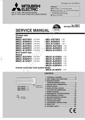
Mitsubishi Electric MUX-A19WV Service Manual (159 pages)
SPLIT-TYPE, AIR CONDITIONERS SPLIT-TYPE, HEAT PUMP AIR CONDITIONERS
Brand:
Mitsubishi Electric
| Category:
Air Conditioner
| Size: 5.12 MB
Table of Contents
Table of Contents
1
Service Manual
1
Technical Changes
2
Information for the Air Conditioner with R410A Refrigerant
3
Conversion Chart of Refrigerant Temperature and Pressure
4
Refrigerant Piping
4
Tools Dedicated for the Air Conditioner with R410A Refrigerant
4
Additional Charge
5
Air Purge
5
Flaring Work and Flare Nut
5
Refrigerant Oil
5
Part Names and Functions
6
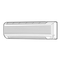
Product View
6
Accessories
7
Outdoor Unit
7
Indoor/Outdoor Correspondence Table
8
Remote Controller
8
Indoor Units Combination
9
Specification
10
Noise Criteria Curves
17
Outlines and Dimensions
20
Wiring Diagram
25
Refrigerant System Diagram
32
Indoor Unit
33
Additional Refrigerant Charge (R410A: G)
34
Max. Height Difference
34
Max. Refrigerant Piping Length
34
Piping Preparation
35
Additional Refrigerant Charge (R410A:g)
37
Max. Refrigerant Piping Length & Max. Height Difference
37
Piping Preparation
37
MSX-A20WV- Additional Refrigerant Charge (R410A:g)
39
MSX-A20WV- Max. Refrigerant Piping Length & Max. Height Difference
39
MSX-A25WV- Additional Refrigerant Charge (R410A:g)
41
MSX-A25WV- Max. Refrigerant Piping Length & Max. Height Difference
41
MSX-A25WV- Piping Preparation
41
MSX-A26WV- Additional Refrigerant Charge (R410A:g)
43
MSX-A26WV- Max. Refrigerant Piping Length & Max. Height Difference
43
MSX-A26WV- Piping Preparation
43
Max. Refrigerant Piping Length - MXY-A18WV -
44
Capacity and the Input Curves
45
How to Measure the Indoor Air Wet-Bulb/Dry-Bulb Temperature Difference
45
Main Readings
45
Performance Curves
45
Outdoor Low Pressure and Outdoor Unit Current Cool Operation
46
Capacity and the Input Curves (One Indoor Unit with Ont Outdoor Unit)
49
Outdoor Low Pressure and Outdoor Unit Current
49
MXZ-A18WV- Capacity and the Input Curves
50
Capacity and Input Correction by Inverter Output Frequency
51
Outdoor Low Pressure and Outdoor Unit Current - 07-Class Unit in Single Operation (OUTDOOR UNIT : MXZ-A18WV)
52
Outdoor Low Pressure and Outdoor Unit Current - 09-Class Unit in Single Operation (OUTDOOR UNIT : MXZ-A18WV)
53
Outdoor Low Pressure and Outdoor Unit Current - 12-Class Unit in Single Operation (OUTDOOR UNIT : MXZ-A18WV)
54
Cool Operation (230V)
55
Msc-A07Wv -
55
Mu-A07Wv -
55
Performance Data
55
Msc-A09Wv -
57
Mu-A09Wv -
57
Msc-A12Wv -
59
Mu-A12Wv -
59
Msc-A07Wv - / Muh-A07Wv -
61
Msc-A09Wv - / Muh-A09Wv -
63
Msc-A12Wv - / Muh-A12Wv -
65
Heat Operation (230V)
67
MSC-A07WV - (Single): MUX-A10WV -
68
Performance Data - COOL Operation (230V)
68
MSC-A07WV -(Single) : MUX-A10WV -
69
MSC-A07WV -(Single : Room B): MUX-A19WV -
70
MSC-A12WV -(Single : Room A): MUX-A19WV -
72
MSC-A09WV -(Single : Room A): MUX-A20WV -
74
MSC-A09WV -(Single : Room B): MUX-A20WV -
76
MSC-A12WV -(Single) : MUX-A25WV -
78
MSC-A09WV -(Single : Room C ): MUX-A26WV -
80
MSC-A12WV -(Single : Room A): MUX-A26WV -
82
Cool Operation
84
Indoor Unit Display Section
84
Microprocessor Control
84
Wireless Remote Controller
84
Coil Frost Prevention
85
Dry Operation
85
Operation Chart
85
Time Control
85
Cold Air Prevention Control
86
Fan Operation
86
Heat Operation
86
Indoor Fan Speed Control
86
High Pressure Protection MUH-A07/A09/A12WV
87
Warm Air Control
87
Defrosting MUH-A07/A09/A12WV
88
"I Feel Control" Operation
89
R.V. Coil Control MUH-A07/A09/A12WV
89
Cool Mode of "I Feel Control"
90
Dry Mode of "I Feel Control"
90
Heat Mode of "I Feel Control" MUH-A07/A09/A12WV
90
The Initial Set Temperature Is Decided by the Initial Room Temperature
90
Auto Vane Operation
91
Fan Motor Control
91
Cold Air Prevention in HEAT Operation MUH-A07/A09/A12WV
92
ECONO COOL Operation (Economical Operation)
92
SWING Operation
92
Timer Operation
92
Emergency Test Operation
93
Program Timer
93
Outdoor Unit Actuator Control
94
Inverter Multi System Control
95
Inverter Main Power Supply Circuit
96
Outline of Main Power Supply Circuit
96
Power-Factor Improvement of Power Supply and Harmonics Control
96
Removal of Electric Noise
96
AFM (Active Filter Module)
97
Function of Main Parts
97
Ipm
97
Optimal Voltage Control
97
Determination of LEV Standard Opening in each Indoor Unit
98
LEV Control
98
LEV Opening Correction by Suction Super Heat (COOL, DRY)
99
Separate Correction (COOL,DRY)
99
Conditions to Finish Defrosting Mode
100
Heat Defrosting Control
100
LEV Opening Correction by Discharge Temperature
100
Operational Frequency Range
100
Discharge Temperature Protection Control
101
Outdoor Fan Control
101
Refrigerant Recovery Control on Heating
101
Relation between Main Sensor and Actuator
101
Change in Defrost Setting MUH-A07/A09/A12WV
102
P.C. Board Modification for Individual Operation
102
Service Functions
102
Timer Short Mode
102
MU & MUXTYPE/MUH & MXZ Type Switch over and Auto Restart Function
103
Remote Controller (How to Set the Type)
103
Cautions on Troubleshooting
104
How to Replace Batteries
104
Troubleshooting
104
Troubleshooting Procedure
104
Instruction of Troubleshooting
105
Self Check Table
107
Troubleshooting Check Table
107
Trouble Criterion of Main Parts
109
Indoor Unit Operates by Pressing the EMERGENCY OPERATION Switch, but Doesn’t Operate with the Remote Controller
112
When OPERATION INDICATOR Lamp Flashes 3-Time; Indoor Fan Motor Doesn’t Operate
112
Compressor And/Or Outdoor Fan Motor Doesn’t Operate
113
The Unit Doesn’t Operate with the Remote Controller
113
Compressor And/Or Outdoor Fan Doesn’t Operate
114
Compressor And/Or Outdoor Fan Motor Doesn’t Stop
115
Unit Operates COOL Mode Even if It Is Set to HEAT Mode
116
Unit Operates HEAT Mode Even if It Is Set to COOL Mode
116
When OPERATION INDICATOR Lamp Flashes 0.5-Second Intervals or 1-Time; Outdoor Unit Does Not Operate
117
Cool Air Does Not Blow out Although Indoor Unit Is Operating
118
When OPERATION INDICATOR Lamp Flashes 6-Time; Thermistors in the Outdoor Unit Are Abnormal
118
Outdoor Unit Does Not Operate. (LED Display: both LED1 and LED2 Lighting)
119
Outdoor Unit Does Not Operate. (LED Display: Display OFF)
119
The Cooling Operation or Heating Operation Does Not Operate. (LED Display: both LED1 and LED2 Lighting)
120
When Cooling, Heat Exchanger of Non-Operating Indoor Unit Frosts/When Heating, Non-Operating Indoor Unit Get Warm
121
When Heating, Room Does Not Get Warm/When Cooling, Room Does Not Get Cool
121
Fan Motor Does Not Operate or Stops Operating Shortly after Starting the Operation
122
When Thermistor Is Abnormal.
122
Indoor Unit Dose Not Operate. (Different Modes)
123
Q Q the Other Cases MXZ-A18WV
123
Indoor Electronic Control P.C. Board
124
Test Point Diagram and Voltage
124
Outdoor Deicer P.C. Board
125
Outdoor Control P.C. Board
126
Outdoor Electronic Control P.C. Board
127
Outdoor Noise Filter P.C.board
128
"Terminal with Lock Mechanism" Detaching Points
129
Disassembly Instructions MSC-A07WV -MSC-A09WV -MSC-A12WV -
129
Removing the Electronic Control P.C. Board and the Power Monitor, Receiver P.C. Board
129
Removing the Front Panel (Indoor Unit)
129
Removing the Electrical Box
130
Removing the Indoor Fan Motor and the Line Flow Fan
130
Removing the Nozzle Assembly and the Vane Motor
130
Removing the Cabinet (Outdoor Unit)
131
Removing the Electrical Parts (Outdoor Unit)
131
Removing the Compressor
132
Removing the Propeller Fan and the Outdoor Fan Motor
132
Disassembly Instructions MUX-A10WV -
135
Disassembly Instructions - MUX-A19WV - MUX-A20WV - MUX-A25WV - MUX-A26WV -
137
Disassembly Instructions - MXZ-A18WV -
140
Accessory and Remote Controller
144
Indoor Unit Structural Parts
144
Parts List
144
Indoor Unit Electrical Parts and Functional Parts
145
Indoor Unit Heat Exchanger
145
Outdoor Unit Structural Parts
146
Outdoor Unit Electrical Parts and Functional Parts
147
Outdoor Unit Structural Parts - MUH-A07WV - MUH-A09WV - MUH-A12WV -
148
Accessory - MUH-A07WV - MUH-A09WV - MUH-A12WV -
149
Outdoor Unit Electrical Parts and Functional Parts - MUH-A07WV - MUH-A09WV - MUH-A12WV -
149
Outdoor Unit and Structural Parts - MUX-A10WV -
150
Outdoor Unit Electrical Parts and Functional Parts - MUX-A10WV -
151
Outdoor Unit Structural Parts - MUX-A19WV - MUX-A20WV - MUX-A25WV - MUX-A26WV -
152
Outdoor Unit Functional Parts and Electrical Parts - MUX-A19WV - MUX-A20WV - MUX-A25WV - MUX-A26WV -
154
Outdoor Unit Functional Parts and Electrical Parts - MXZ-A18WV -
155
Outdoor Unit Functional Parts and Structural Parts - MXZ-A18WV -
156
Air Cleaning Filter
157
Deodorizing Filter
157
Different-Diameter Pipe
157
Optional Parts
157
Advertisement
Mitsubishi Electric MUX-A19WV Service Manual (158 pages)
SPLIT-TYPE, AIR CONDITIONERS; SPLIT-TYPE, HEAT PUMP AIR CONDITIONERS
Brand:
Mitsubishi Electric
| Category:
Air Conditioner
| Size: 5.28 MB
Table of Contents
Table of Contents
1
Technical Changes
2
Part Names and Functions
6
Correspondence Table
8
Indoor/Outdoor
8
Indoor Units Combination
9
Specification
10
Noise Criteria Curves
17
Outlines and Dimensions
20
Wiring Diagram
25
Refrigerant System Diagram
32
Performance Curves
45
Microprocessor Control
84
Service Functions
102
Troubleshooting
104
Disassembly Instructions
129
Parts List
144
Optional Parts
157
Advertisement
Related Products
Mitsubishi Electric MUX-A10WV
Mitsubishi Electric MUX-A20WV
Mitsubishi Electric MUX-A25WV
Mitsubishi Electric MUX-A26WV
Mitsubishi Electric MUX-A10WV-E1
Mitsubishi Electric MUX-A19WV-E1
Mitsubishi Electric MUX-A20WV-E1
Mitsubishi Electric MUX-A25WV-E1
Mitsubishi Electric MUX-A26WV-E1
Mitsubishi Electric MUX-19TV - E1
Mitsubishi Electric Categories
Air Conditioner
Controller
Projector
Inverter
Heat Pump
More Mitsubishi Electric Manuals
Login
Sign In
OR
Sign in with Facebook
Sign in with Google
Upload manual
Upload from disk
Upload from URL