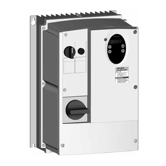
Toshiba Tosvert VF-S11 Instruction Manual Supplement
Toshiba tosvert vf-s11 totally-enclosed box type inverter
Hide thumbs
Also See for Tosvert VF-S11:
- Instruction manual (269 pages) ,
- Option instruction manual (22 pages) ,
- Specifications (12 pages)
Advertisement
Quick Links
E6581225
Instruction Manual (Supplementary)
Totally-Enclosed Box Type Inverter
VF-S11
TOSVERT
Thank you for purchasing a Toshiba "totally-enclosed box type TOSVERT VF-S11 series inverter."
This Manual gives a supplementary explanation of some items referred to in the instruction manual E6581158
included with the product. Please read this manual carefully along with the instruction manual E6581158.
- To set makers -
Please see to it that this manual is supplied to the inverter's end user, along with the instruction manual
E6581158.
CT Automatismos y Procesos, S.L. • Vía Trajana, 50- 56, Nave 42
08020 Barcelona • Tel: 902 44 50 50 • Fax: 902 12 03 69
•
www.ctautomatismos.com
automatismos@ctautomatismos.com
Advertisement

Summary of Contents for Toshiba Tosvert VF-S11
- Page 1 VF-S11 TOSVERT Thank you for purchasing a Toshiba “totally-enclosed box type TOSVERT VF-S11 series inverter.” This Manual gives a supplementary explanation of some items referred to in the instruction manual E6581158 included with the product. Please read this manual carefully along with the instruction manual E6581158.
- Page 2 E6581225 Safety precautions Before reading this manual, please read the following instructions in addition to “I. Safety Precautions,” of the instruction manual E6581158. General Operation Danger • Circuit boards are exposed when the front cover is removed. So do not detach the front Mandatory cover when the inverter is energized or within 10 minutes after power is turned off.
- Page 3 Note 1: The switch has the function of tripping (overcurrent tripping). If the switch is in the Trip position, inspect the inverter before turning back on the power switch, because the inverter itself may be faulty. Note 2: Recommended contact input switches: Harmony series (XB5 series) manufactured by Toshiba Schneider Inverter Corporation...
- Page 4 E6581225 Main circuit and control circuit terminal boards Control signal cable connector To front cover Screw Screw Internal cooling fan Control circuit terminal board Screw Screw Main circuit terminal board 2 Main circuit terminal board 1 Motor output : U, V, W, PE Power supply : R, S, T Internal DC section : P0, PA/+, (Single-phase : R, S)
- Page 5 E6581225 Wiring diagram (1) Input power cable (2) Output cable (3) Control cable (4) Control resistor (optional) cable (5) Wiring port plate (6) Grounding terminal (7) Optional communications device interconnect cable (Option) Cautions • Circuit boards are exposed when the front cover is removed. Since high voltages are applied to some parts of the circuit board, read Section 2.1, “Cautions on wiring,”...
- Page 6 E6581225 Diagram of cables connected at the factory VIB CC White Blue Blue Potentiometer for frequency setting Operation ON-OFF rotary switch Note: The colors indicated in the above figure refer to the colors of cables. Installation environment • Operate in areas where ambient temperature ranges from -10°C to +40°C.
- Page 7 E6581225 Outside dimensions Applicable Outside dimensions (mm) Voltage Motor Inverter type Cable port class VFS11S-2002PLE φ 19 × 3 VFS11S-2004PLE φ 21 × 1 1-phase 0.75 VFS11S-2007PLE 200V VFS11S-2015PLE φ 19 × 1 φ 23 × 3 VFS11S-2022PLE VFS11-2004PME φ 19 × 3 φ...
-
Page 8: Specifications
E6581225 Specifications Item Specification Voltage class 1-phase 200V class/3-phase 200V class/3-phase 400V class Applicable motor (kW) 0.75 Voltage class Model number VFS11S-/VFS11- 1-phase 200V class VFS11S- 2002PLE 2004PLE 2007PLE 2015PLE 2022PLE 3-phase 200V class VFS11- 2004PME 2007PME 2015PME 2022PME 2037PME 3-phase 400V class VFS11- 4004PLE...


