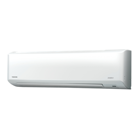
Summary of Contents for Toshiba RAS-13N3KV Series
- Page 1 INSTALLATION MANUAL ENGLISH AIR CONDITIONER (SPLIT TYPE) Indoor unit RAS-13N3KV Series Outdoor unit RAS-13N3AV Series 11155 51106...
-
Page 2: Table Of Contents
CONTENTS 安全預防措施 ....................1 PRECAUTIONS FOR SAFETY ..............1 室內與室外機組的安裝圖 ................2 INSTALLATION DIAGRAM OF INDOOR AND OUTDOOR UNITS ....2 選購性安裝零部件 ..................2 Optional Installation Parts .................2 室內機組 .......................3 INDOOR UNIT ....................3 安裝地點 ....................3 Installation Place ..................3 鑽孔及安置安裝板 ..................3 Cutting a Hole and Mounting Installation Plate .........3 線路連接... -
Page 3: Precautions For Safety
PRECAUTIONS FOR SAFETY PRECAUTIONS FOR SAFETY For general public use Power supply cord of parts of appliance for outdoor use shall be at least polychloroprene sheathed fl exible cord (design H07RN-F) or cord designation 60245 IEC66 (1.5 mm or more). (Shall be installed in accordance with national wiring regulations.) New refrigerant air conditioner installation CAUTION •... -
Page 4: Installation Diagram Of Indoor And Outdoor Units
INSTALLATION DIAGRAM OF INDOOR AND OUTDOOR UNITS INSTALLATION DIAGRAM OF INDOOR AND OUTDOOR UNITS For the rear left and left piping Hook Installation plate Wall Insert the cushion between the indoor unit and wall, and tilt the indoor unit for better operation. -
Page 5: Indoor Unit
INDOOR UNIT INDOOR UNIT When the installation plate is directly mounted Installation Place on the wall • A place which provides the spaces around the indoor unit as shown in the 1. Securely fi t the installation plate onto the wall by screwing it in the upper and diagram lower parts to hook up the indoor unit. -
Page 6: How To Connect Remote Controller For Wire Operation
Connecting cable 70 mm * Wire size 28-22AWG Terminal block or 0.08-0.32 mm Outer diameter not over 4.7 mm, Cord Terminal control wire length less than 30 m. clamp cover 5 mm Notch for wire out Screw Screw Earth line 100 mm 10 mm Tighten fi... -
Page 7: Piping And Drain Hose Installation
Battery cover 2) Firmly insert the drain cap. Screw Tighten fi rmly but not over No gap 0.15 N.m (0.02 kgf.m) Do not apply lubricating oil (refrigerant machine oil) when inserting the drain cap. Application causes deterioration and drain leakage of the plug. Insert a hexagon wrench (4 mm). -
Page 8: Indoor Unit Fixing
Do not form the Indoor Unit Fixing Do not rise the drain hose into drain hose. a wavy shape. 1. Pass the pipe through the hole in the wall and hook the indoor unit on the 50 mm installation plate at the upper hook. or more 2. -
Page 9: Evacuating
Tightening connection Compound pressure gauge Pressure gauge –101 kPa (–76 cmHg) Align the centers of the connecting pipes and tighten the fl are nut as far as Manifold valve possible with your fi ngers. Then tighten the nut with a spanner and torque Handle Hi wrench as shown in the fi... -
Page 10: Wiring Connection
Model RAS-13N3KV Series Wiring Connection Power source 50Hz, 220 – 240 V Single phase Maximum running current 9.1A 1. Remove the valve cover from the outdoor unit. Circuit breaker 12.0A 2. Connect power cord to the terminal block L, N and... -
Page 11: 安全預防措施
安全預防措施 安全預防措施 供一般公眾使用 室外機組各部分的電源線應至少是聚氯丁二烯護套軟線 (H07RN-F) 或指定電纜 60245 IEC66 (1.5 mm 或以上)。(必須按照照 國家布線規則進行安裝。) 新型冷凍劑空調器的安裝 注 意 ● 本空調器採用新型 HFC 冷凍劑 (R410A),該冷凍劑不會損耗臭氧層。 由於 R410A 冷凍劑的壓力約 為 R22 冷凍劑的 1.6 倍,因此很容易受到水、氧化膜和油等雜質的影響。也由於採用了此新型冷 凍劑,冷凍機油也需要改變。因此,在安裝作業中,應確保水、灰塵、原來的冷凍劑或冷凍機油不能進入新型冷凍劑空調器 的冷凍循環中。 為 避免冷凍劑與冷凍機油混合,主機上連接部分的加注口尺寸與常規冷凍劑的加注口尺寸不同,需要不同尺寸的工具。對於 連接導管,請使用新的、乾淨的,能承受高壓的 R410A 專用管材,並確保水、灰塵沒有進入。此外,切勿使用已有的任何配 管,因 為 其承受壓力可能不足,且可能含有雜質。 從主電源上斷開此設備 注 意 本設備必須通過斷路器或者所有電極至少保持 3 mm 接觸間隔的切換開關連接到主電源。 此安裝斷路器為本空調供電線路專 用。 危 險 ● 僅由合資格者使用。... -
Page 12: 室內與室外機組的安裝圖
室內與室外機組的安裝圖 室內與室外機組的安裝圖 供左後及左配管。 掛鉤 安裝板 牆 請在室內機組和牆壁之間插入 墊子 , 並且提起室內機組以使 工作更容易。 請勿讓排水管鬆馳。 稍微傾斜地 遮護管 切割管孔。 過濾器 請務必讓排水管向下方傾斜運行。 輔助管可連接在左、左後、右後、右、 平頭木螺釘 遙控器支座 右底或左底部位。 進行完排水測試後 , 用 纖維尼龍膠帶來包裹。 平頭木螺釘 電池蓋 右 & 右後 無線遙控器 平頭木螺釘 左 右底 左後 左底 管子夾頭 電池 用絕緣材料分別地為冷凍劑配 管絕緣 , 而非一起進行。 延長排水管... -
Page 13: 室內機組
室內機組 室內機組 當直接安裝安裝板到牆上時 安裝地點 1. 通過用螺絲釘住上面和下面的部份來將安裝板牢牢圍住在牆 ● 在室內機周圍有如圖所示空間的地方 上以掛鉤住室內機組。 ● 在空氣進出口附近無障礙物之處 2. 若要在混凝土牆上用錨狀螺栓固定安裝板 , 請使用下圖中所 ● 方便安裝配管至室外機之處 示的錨栓孔。 ● 可打開前面板之處 3. 將安裝板打橫式安裝於牆上。 ● 室內機的安裝應使其頂部位置至少在 2 米高處。同樣 , 必須 避免在室內機的頂部放置任何東西。 注 意 當用安置螺釘來安裝安裝板時 , 切勿用錨狀螺栓孔。否則 , 注 意 本機可能摔落而致傷人或造成財物損失。 ● 應避免陽光直接照射到室內機組的無線接收器。... -
Page 14: 如何連接遙控器為有線操作
連接電纜 70 mm * 導線尺寸 28-22AWG 電線夾 或 0.08-0.32 mm 外直徑不超過 4.7 mm, 控制線長度不超過 30 m。 螺釘 端子蓋 5 mm 出線凹槽 螺釘 螺釘 接地線 100 mm 10 mm 請加緊,但力矩不 終端 要超過 0.12 N·m 控制線 (0.01 kgf·m) 10 mm 控制線 90 mm 連接電纜的剝除長度 遙控器凹槽 備 注 ● 只能使用絞合電線。... -
Page 15: 配管與排水管的安裝
電池蓋 2) 穩固插入排水蓋。 螺釘 請加緊,但力矩不要超過 0.15 N·m (0.02 kgf·m) 無間隙 在插入排水蓋時 , 切勿塗抹潤滑油 (冷凍機油) , 否則會造成插頭老化 和排水滲漏。 插入六角形扳手 (4 mm)。 注 意 穩固地插入排水管和排水蓋 , 否則會產生漏水。 *注意: 1. 建議使用雙重絕緣導線連接遙控器和空調。 2. 對於有線操作,1 個遙控器僅可控制 1 個室內單 進行在右或左配管安裝時 元。 ● 在用小刀或斷離針將裂口劃破後 , 3. 有線操作中,當用戶關閉空調電源的時候,遙控器 將返回至初始條件(預設置、計時器和時鐘將返回 再用一對剪鉗或類似工具將其剪 初始條件)。 下。 如何在室內機組上安裝空氣入口格柵 裂口... -
Page 16: 固定室內機組
固定室內機組 請勿將排水管 請勿抬高排水管。 彎曲成波浪形。 1. 將管子穿過牆上的洞並讓室內機組掛鉤住安裝板稍高處的掛 50 mm 鉤。 或以上 2. 向左和右擺筋室內機組以確它已牢固地掛鉤在安裝板上。 3. 將室內機組壓向牆面以讓它掛鉤住安裝板的較低部份。向您 所在方向拉動本機以確定它已牢因地掛鉤在安裝板上。 請勿將排水管的 請勿將排水管的尾 尾端浸於水中。 端置於水溝中。 掛在此。 安裝板 2. 放水到排水盤中並確定水已排出到室外。 3. 當連接延長排水管時 , 請用遮護管絕緣延長排水管的連接部 份。 掛鉤 按 遮護管 (從掛鉤上取下) ● 要從安裝板上拆下室內機時 , 請在 所指定的部件處向上推起室內機的 延長排水管 房間內 排水管 底部 , 然後朝您的方向拉出即可。 注 意 推 推... -
Page 17: 電氣工作
緊固連接 復合壓力表 壓力表 –101 kPa 校正連接管的中心並用手指盡量擰緊擴口螺母。然後用圖中所 (–76 cmHg) 岐管表 示的扳手和扭矩扳手鎖緊。 高壓側把手 低壓側把手 (保持完全關閉) 充氣管 半聯合 擴口螺母 (僅適用於 R410A) 充氣管 連接管 (僅適用於 R410A) 外部螺紋側 內部螺紋側 用於防逆流的 真空泵適配器 使用扳手緊固。 使用扭矩扳手緊固。 (僅適用於 R410A) 注 意 真空泵 切勿過份扭動。否則 , 視情況而定 , 螺母可能破裂。 氣體側的壓縮閥 (單位: N·m) 維修口 (閥心 (調節針)) 銅管的外圈直徑 緊固扭矩 液體側的壓縮閥... -
Page 18: 線路連接
線路連接 機型 RAS-13N3KV Series 電源 50Hz, 220 – 240 V 單相 1. 從室外機組上移走閥門蓋。 最大運行電流 9.1A 、 和 處,然後依照室內與室 2. 將電源線連接至端子板 斷路器 12.0A 外機組端子板上所標示的相應匹配號碼,將連接電纜連接至 電源線 H07RN-F 或 60245 IEC66 (1.5 mm 或以上) 端子。 連接電纜 H07RN-F 或 60245 IEC66 (1.5 mm 或以上) 3. 請將不使用的電線 (導體) 與任何進入室外機的水隔開。處 理後使其不與任何電氣或金屬部件接觸。 注 意... - Page 20 11155 51106...


