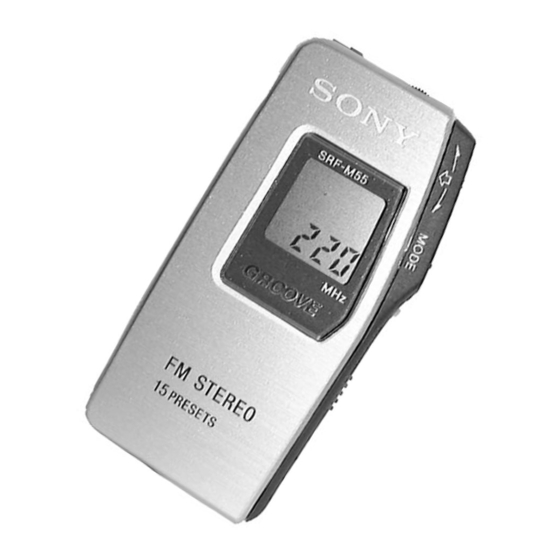
Summary of Contents for Sony SRF-M55
- Page 1 SRF-M55 SERVICE MANUAL AEP Model E Model Ver 1.0 1999.09 Chinese Model SPECIFICATIONS FM STEREO PLL SYNTHESIZED RADIO MICROFILM...
-
Page 2: Table Of Contents
TABLE OF CONTENTS Flexible Circuit Board Repairing • Keep the temperature of the soldering iron around 270°C during repairing. Specifications ................1 • Do not touch the soldering iron on the same conductor of the circuit board (within 3 times). 1. -
Page 3: Disassembly
SECTION 2 DISASSEMBLY The equipment can be removed using the following procedure. Cabinet ASSY, Front Main board LCD201 Cabinet ASSY, Rear Microcomputer board Note : Follow the disassembly procedure in the numerical order given. 2-1. “CABINET ASSY, FRONT”, “CABINET ASSY, REAR” Cabinet ASSY, front 2 Claws 5 LCD flexible board (13 core) -
Page 4: Lcd201
2-3. LCD201 LCD201 Cabinet ASSY, front 1 Claws 2-4. MICROCOMPUTER BOARD 1 Screws (1.4) Microcomputer board 4 Claw 4 Claws Cover, side 2 Claws Cabinet ASSY, rear – 4 –... -
Page 5: Adjustments
SECTION 3 ADJUSTMENTS FM Section FM STEREO (19kHz) Adjustment 0 dB=1µV Setting : Setting : FM RF signal FM RF signal generator generator 0.01 µ F 0.01 µ F TP (ANT) TP (ANT) Carrier frequency : 98MHz Modulation : 1kHz, 22.5kHz deviation 22.5kHz frequency deviation by 400Hz signal. -
Page 6: Diagrams
SECTION 4 DIAGRAMS 4-1. EXPLANATION OF IC TERMINALS IC301 µ PD17015GS-556-GJG (SYSTEM CONTROL, LCD DRIVE) Pin No. Pin name Description POB2 Key return input. PCO0 Key source output. PCO1 Key source output. PCO2 Power (AUTO OFF) key input. PCO3 HOLD key input. POD0/BEEP Beep output. -
Page 7: Block Diagrams
SRF-M55 4-2. BLOCK DIAGRAMS • Signal path. : FM – 7 – – 8 – – 9 –... - Page 8 SRF-M55 4-3. PRINTED WIRING BOARDS Semiconductor Location Ref. No. Location D101 F-11 D102 F-11 [MICROCOMPUTER BOARD] [MICROCOMPUTER BOARD] S205(JOG) D301 (SIDE A) [MAIN BOARD] (SIDE B) [MAIN BOARD] (SIDE A) (SIDE B) D303 D305 S202 R118 D306 POWER C123 Q103...
- Page 9 SRF-M55 4-4. SCHEMATIC DIAGRAM Refer to page 10 for Notes. Refer to page 16 for IC Block Diagrams. WAVEFORMS 4.6Vp-p 360 nsec VOLT/DIV : 1 V AC Q301-2 C TIME/DIV : 0.1 µsec 5.2Vp-p 982 nsec VOLT/DIV : 1 V AC T301 TIME/DIV : 0.2 µsec...
-
Page 13: Schematic Diagram
MAIN MICROCOMPUTER Ref. No. Part No. Description Remark Ref. No. Part No. Description Remark 1-412-010-41 INDUCTOR CHIP 22uH < SWITCH > 1-412-987-31 INDUCTOR 4.7uH 1-571-275-11 SWITCH, SLIDE (FM SENS) 1-412-987-31 INDUCTOR 4.7uH 1-571-506-41 SWITCH, SLIDE (GROOVE/MEGA BASS/OFF) 1-412-987-31 INDUCTOR 4.7uH <... - Page 14 SRF-M55 MICROCOMPUTER Ref. No. Part No. Description Remark Ref. No. Part No. Description Remark IC202 8-759-472-77 IC S-80810ANNP-E70-T2 < SWITCH > IC301 8-759-650-20 IC uPD17015GS-556-GJG IC302 8-759-650-21 IC S-8323A25MC-ELF-T2 S201 1-692-088-11 SWITCH, TACTILE (HOLD) S202 1-692-088-11 SWITCH, TACTILE (POWER (AUTO OFF)) <...


