Advertisement
AIR CONDITIONER (MULTI-SPLIT TYPE)
Installation Manual
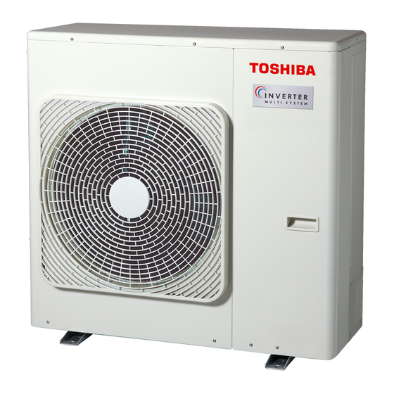
Outdoor Unit
Model name:
RAS-3M26U2AVG-E
RAS-4M27U2AVG-E
RAS-5M34U2AVG-E
* NOTE:
Descriptions about operations for the E unit in this manual are
not applicable to RAS-4M27U2AVG-E.
Descriptions about operations for the D unit and the E unit in
this manual are not applicable to RAS-3M26U2AVG-E.
Installation Manual
Outdoor Unit
R32
English
Advertisement
Table of Contents

Summary of Contents for Toshiba RAS-4M27U2AVG-E
- Page 1 RAS-4M27U2AVG-E RAS-5M34U2AVG-E * NOTE: Descriptions about operations for the E unit in this manual are not applicable to RAS-4M27U2AVG-E. Descriptions about operations for the D unit and the E unit in this manual are not applicable to RAS-3M26U2AVG-E. Installation Manual...
-
Page 2: Table Of Contents
Outdoor Unit Installation Manual Contents Precautions for safety ..................................2 Installation / service tools .................................. 8 Specifi cations ....................................8 Optional parts, accessories ................................8 Installation of outdoor unit ................................9 Refrigerant piping ....................................10 Electrical work ....................................13 Grounding ......................................14 Test run ....................................... 14 10. -
Page 3: Precautions For Safety
Outdoor Unit Installation Manual 1 P recautions for safety The manufacturer shall not assume any liability for the damage caused by not observing the description of this manual. Be sure to read this installation manual carefully before installing. The supplied CD-ROM contains the installation manual translated into many languages. Recommend to the owner to perform maintenance periodically when using over long periods of time. - Page 4 Outdoor Unit Installation Manual CAUTION To disconnect the appliance from the main power supply This appliance must be connected to the main power supply by means of a circuit breaker or a switch with a contact separation of at least 3 mm in all poles. CAUTION NEW REFRIGERANT AIR CONDITIONER INSTALLATION THIS AIR CONDITIONER USES THE NEW HFC REFRIGERANT (R32), WHICH...
- Page 5 Outdoor Unit Installation Manual DANGER • WHEN MOVING THE AIR CONDITIONER FOR INSTALLING IT IN ANOTHER PLACE AGAIN, BE VERY CAREFUL NOT TO GET THE SPECIFIED REFRIGERANT (R32) WITH ANY OTHER GASEOUS BODY INTO THE REFRIGERATION CYCLE. IF AIR OR ANY OTHER GAS IS MIXED IN THE REFRIGERANT, THE GAS PRESSURE IN THE REFRIGERATION CYCLE BECOMES ABNORMALLY HIGH AND IT RESULTANTLY CAUSES BURST OF THE PIPE AND INJURIES ON PERSONS.
- Page 6 Outdoor Unit Installation Manual WARNING • Do not use any refrigerant different from the one specifi ed for complement or replacement. Otherwise, abnormally high pressure may be generated in the refrigeration cycle, which may result in a failure or explosion of the product or an injury to your body. •...
- Page 7 Outdoor Unit Installation Manual WARNING • If you detect any damage, do not install the unit. Contact your supplying dealer immediately. • Never modify this unit by removing any of the safety guards or bypassing any of the safety interlock switches.
- Page 8 Outdoor Unit Installation Manual Requirement of report to the local power supplier Please make absolutely sure that the installation of this appliance is reported to the local power supplier before installation. If you experience any problems or if the installation is not accepted by the supplier, the service agency will take adequate countermeasures.
-
Page 9: Installation / Service Tools
16 or 18 or 22 or 24 6.35, 12.7 mm *2 Need the reducer (12.7 to 9.52 mm). 68 (RAS-5M34U2AVG-E ) *3 Need the expander (9.52 to 12.7 mm). Total 54 (RAS-4M27U2AVG-E ) — • Locally procured. 54 (RAS-3M26U2AVG-E) O ptional parts, accessories Optional parts... -
Page 10: Installation Of Outdoor Unit
Outdoor Unit Installation Manual Draining Off the Water from the Outdoor Unit Installation of outdoor unit Install 5 waterproof rubber caps and the drain nipple to drain off the 7 Installation Location water from the outdoor unit. • Seal the knock-out holes and screw/thread areas tightly using a silicon •... -
Page 11: Refrigerant Piping
Outdoor Unit Installation Manual Refrigerant piping CAUTION CAUTION • KEEP IMPORTANT 6 POINTS FOR PIPING WORK. Install in rooms that are 13 m or larger. If (1) Take away dust and moisture (inside a leak of refrigerant gas occurs inside the of the connecting pipes). - Page 12 Outdoor Unit Installation Manual 7 Gas Leak Inspection 6. Tighten all the caps on the valves securely, then perform a gas leak inspection. • The cap with the 9.52 mm outer diameter is available in two sizes in • Perform a gas leak inspection for the flare nut connections, valve stem accordance with the type of packed valve for which the cap is used.
- Page 13 Outdoor Unit Installation Manual 1. Detach the front panel. Do not remove the air discharge grille. 2. Turn on the circuit breaker to supply electricity. In the initial LED display status, D805 is lighted as below. ○ : ON, ● : OFF, ⌾ : Rapid Flashing (5 times/sec.), ◇...
-
Page 14: Electrical Work
Outdoor Unit Installation Manual 7 Wire Connection E lectrical work • The dash lines show on-site wiring. WARNING For indoor unit RAS-M series. (System • Be sure to comply with local regulations/ (Main circuit) interconnection wires) codes when running the wire from the Input power outdoor unit to the indoor unit. -
Page 15: Grounding
4. Press the SW801 4 times until the LED is displayed as below. Connecting cable (D unit) D800 D801 D802 D803 D804 D805 * Connection example (RAS-4M27U2AVG-E) ● ● ○ ● ⌾ ● 5. Press SW802 for 1 times. Then D805 light is fl ashing (5 times/sec.). - Page 16 Outdoor Unit Installation Manual ■ Gas Leak Inspection ○ : ON, ● : OFF, ⌾ : Rapid Flashing (5 times/sec.), ◇ : Slow Flashing (1 time/sec.) ■ Refer to the “ Gas Leak Inspection” on page 11. Description ■ Test run D800 D801 D802 D803 D804 D805 Normal operation (no error) 1.
-
Page 17: Appendix
Outdoor Unit Installation Manual... - Page 18 144 / 9 Moo 5, Bangkadi Industrial Park, Tivanon Road, Tambol Bangkadi, Amphur Muang, Pathumthani 12000, Thailand 1116791098...


